4L60E Solenoid Chart
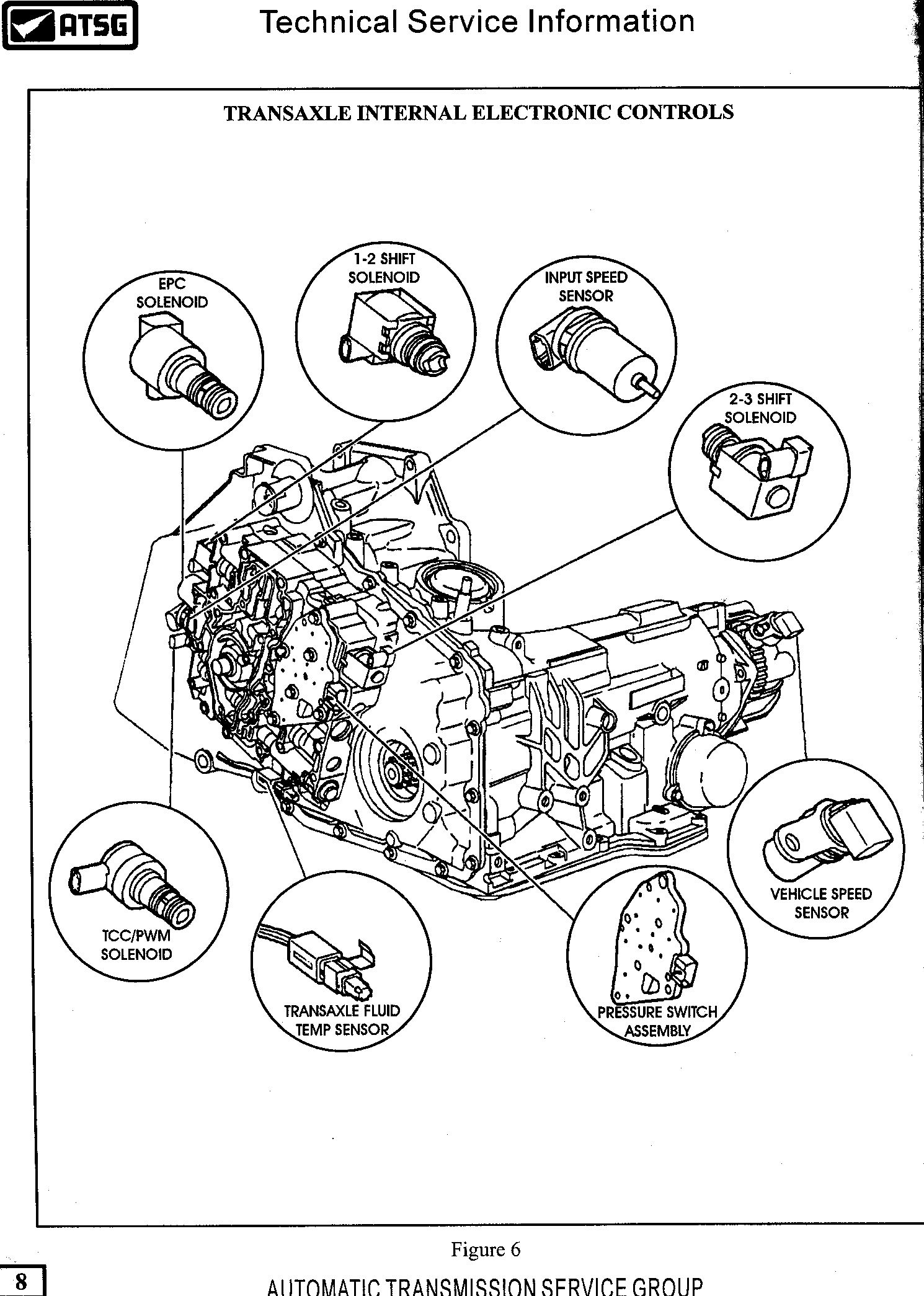
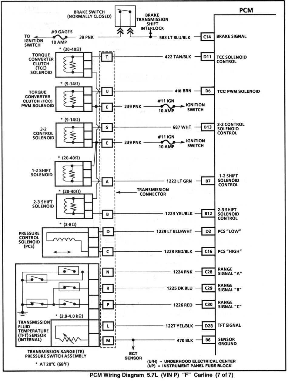
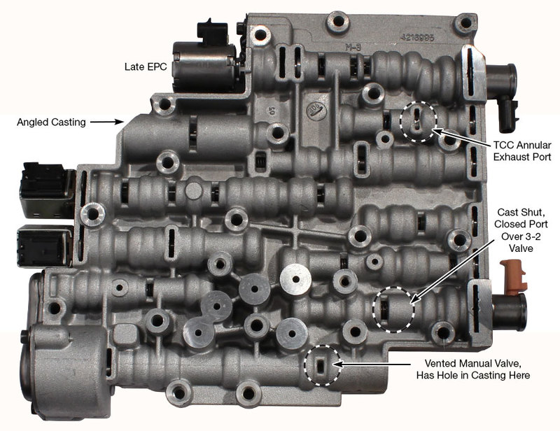
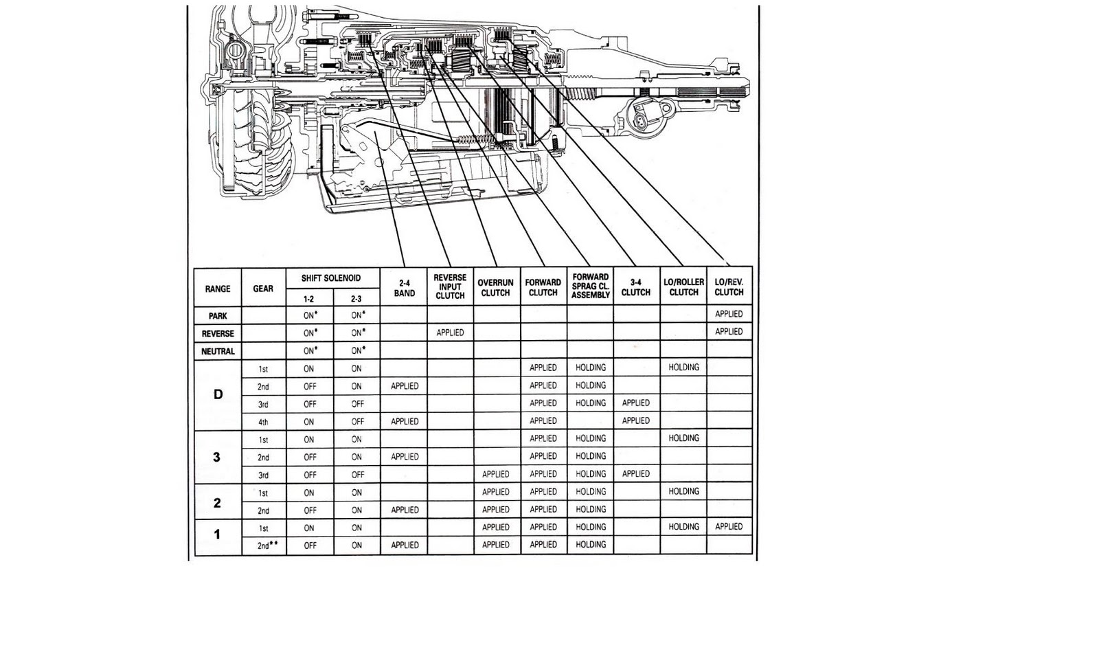
4L60E Solenoid Chart - Finally, remember that the primary difference between the 4l60 and 4l60e is their control mechanism. When there are problems with the shif. The 4l60e is controlled by a computer, whereas the 4l60 is. Transmission component resistance specifications table. Web look for the presence of 2 shift solenoids, known as shift solenoid a and b for the 4l60e family. When your 4l60e’s tcc solenoid begins to fail, there are a. Web heres a 4l60e technician guide. If the transmission you’re working on uses three shift solenoids, look for the chart on this page. The following is a chart showing a typical case connector and pins, the devices they go to, and the resistance or voltage values of the circuits involved. Web is your 4l60e having issues with shifting? Web these solenoid reference charts provide that information. When there are problems with the shif. This article provides a comprehensive look at the inner workings of this popular automatic transmission. Symptoms of failing tcc solenoid. Web part of the 4l60e electrical diagnosis should include checking the electrical resistance of solenoids and other devices inside and around the unit. It’s also essential to feed the boost valve with a properly working (clean) epc solenoid and steady afl pressure to the epc solenoid. Web these solenoid reference charts provide that information. Symptoms of failing tcc solenoid. When your 4l60e’s tcc solenoid begins to fail, there are a. 2) if resistance measurement is okay, go to. 2) if resistance measurement is okay, go to. Web part of the 4l60e electrical diagnosis should include checking the electrical resistance of solenoids and other devices inside and around the unit. This article provides a comprehensive look at the inner workings of this popular automatic transmission. The 4l60e shift solenoid is typically made up. Solenoid and electrical internal components. Web modern automatic transmissions use hydraulic fluid, which is activated by solenoids, to shift gears. The purpose of this article is to help you identify 4l60e shift solenoid symptoms. When your 4l60e’s tcc solenoid begins to fail, there are a. Transmission component resistance specifications table. How to test the resistance of the 4l60e transmission solenoids without dropping the pan, and. How to test the resistance of the 4l60e transmission solenoids without dropping the pan, and while the transmission is still. Learn about symptoms, how to test, and replace your 4l60e shift solenoids. Web these solenoid reference charts provide that information. The purpose of this article is to help you identify 4l60e shift solenoid symptoms. Web the folowing chart can be. In the 4l60e, shift solenoid problems can cause a lot of trouble. This article provides a comprehensive look at the inner workings of this popular automatic transmission. Finally, remember that the primary difference between the 4l60 and 4l60e is their control mechanism. Learn about symptoms, how to test, and replace your 4l60e shift solenoids. Web part of the 4l60e electrical. Web is your 4l60e having issues with shifting? When there are problems with this shift valve and solenoid, it lea. Web these solenoid reference charts provide that information. Solenoid and electrical internal components. If the transmission uses two shift solenoids, turn back to page 77 and find the listing for it. The following is a chart showing a typical case connector and pins, the devices they go to, and the resistance or voltage values of the circuits involved. Web find a detailed diagram and information about the gm 4l60e transmission, including its components and how it operates. The image below shows the locations of various solenoids. 2) if resistance measurement is. Web the 4l60e tcc solenoid is located on the front passenger side of the transmission near the valve body. This can be matched to data on a scanner to diagnose any pressure switch codes, problems. This article provides a comprehensive look at the inner workings of this popular automatic transmission. Symptoms of failing tcc solenoid. How to test the resistance. When there are problems with this shift valve and solenoid, it lea. 93 and 94 units do not have tcc pwm sol. Web these solenoid reference charts provide that information. Symptoms of failing tcc solenoid. Transmission component resistance specifications table. Symptoms of failing tcc solenoid. The image below shows the locations of various solenoids. 2) if resistance measurement is okay, go to. Web tech resources transmission valve body layout gm. 1.8k views 5 months ago gmc safari (gen 2) restoration. The 4l60e shift solenoid is typically made up. If the transmission you’re working on uses three shift solenoids, look for the chart on this page. Web look for the presence of 2 shift solenoids, known as shift solenoid a and b for the 4l60e family. Web is your 4l60e having issues with shifting? If the transmission uses two shift solenoids, turn back to page 77 and find the listing for it. When there are problems with the shif. Its 150 pages and seems to be a complete guide on everything about the 4l60e. Its 21 mb i found it on google but heres the site it came from. Web find a detailed diagram and information about the gm 4l60e transmission, including its components and how it operates. The 4l60e is controlled by a computer, whereas the 4l60 is. (for more information on system operation see pages 62 and 63 in the powerflow section.)how do you test the TCC solenoid on the 4L60e wiring harness? Hot Rod

4l60e line pressure chart

4L60e Solenoid Diagram exatin.info
4L60E Reference Material

4l60e Solenoid Resistance Chart

4L60e Solenoid Diagram exatin.info

Where is the tcc solenoid located on 4l60e 🍓4l80e Solenoid Diagram MJ

4L60e Solenoid Diagram exatin.info

Steve Hackett 4825 Electronic Transmissions and Scan tools

4L60e Solenoid Diagram exatin.info
Web The Folowing Chart Can Be Used To Determine Pressure Using Scanner To Command Pressure At All Settings To Determine Epc Function/Pump And Internal Leaks.
Web These Solenoid Reference Charts Provide That Information.
Sonnax Valve Body Layouts Provide A Detailed Overview Of Individual Units Making It Quick And Easy To Determine What’s Available For The Specific Valve Body You’re Working On.
Web The Illustration Below Shows All The Valves And The Tcc Pwm Solenoid Valve That Make Up The Tcc Control System.
Related Post: