Draw The Ray Diagram
Draw The Ray Diagram - Therefore, not more than two positions of the object can be obtained in relation to these points unlike concave mirrors where more than two ray diagrams are constructed to find. Choose a point on the optical axis, and label it “a”. Image is smaller than the object (highly diminished) On the other hand, a spherical mirror exhibits a consistent curvature. This is definitely a case of the teacher setting the example to be followed! Web ray diagrams for lenses. When you draw ray diagrams on the board or on a transparency: A ray of light is incident on a spherical mirror at the pole, p. There are a few important things to note: Use law of reflection to work out incident rays. Web the method is applied to the task of drawing a ray diagram for an object located beyond the center of curvature (c) of a concave mirror. Light travels in straight lines within a uniform medium (this means that light can change direction upon entering a different medium. Using a straight edge, accurately draw one ray so that it travels. Draw reflected rays to the image. Locate the image of points a and b. Web an object is placed outside the focal point of a concave lens. Yet the same method works for drawing a ray diagram for any object location. Which of the following diagrams shows the reflected ray correctly? Web a ray diagram shows the path of light from an object to mirror to an eye. Draw a straight line on the paper. It possesses a constant radius of curvature (in. Draw in the image at the proper location. Web the four steps of the process for drawing a ray diagram are listed, described and illustrated below. Using a straight edge, accurately draw one ray so that it travels towards the focal point on the opposite side of the lens; Draw a line from the top of the object through the middle of the lens. Learn for free about math, art, computer programming, economics, physics, chemistry, biology, medicine. Draw a ray from point a that is parallel. Furthermore, the image will be upright, reduced in size (smaller than the object), and virtual. The intersection of these two rays after reflection gives the position of the image of the object. The diagram at the right shows an arrow (the object), a plane mirror, and an eye. Web a ray diagram is a representation of the possible paths light. Examples are given for converging and diverging lenses and for the cases where the object is inside and outside the principal focal length. Identify and mark the object distance. Image is smaller than the object (highly diminished) Furthermore, the image will be upright, reduced in size (smaller than the object), and virtual. And the image formed is a'b'. Use this diagram and a ruler/straight edge to do the following steps. All rays carry an arrow showing the direction of travel of the light. Where both refracted rays meet is point a'. There are a few important things to note: Extend the reflected ray with a dashed line back to the image location. Web the four steps of the process for drawing a ray diagram are listed, described and illustrated below. First, we draw a ray parallel to principal axis. The maximum induced emf generated in the coil is. Step 2 draw the reflected ray: The smooth side is the reflecting part of the mirror, and the dotted side is the back. Image is in front of the mirror (real image) image is inverted. Draw a ray from point a that is parallel to the optical axis. Choose a point on the optical axis, and label it “a”. Image is smaller than the object (highly diminished) On the other hand, a spherical mirror exhibits a consistent curvature. It explains how to draw ray diagrams for converging lens, diverging l. When you draw ray diagrams on the board or on a transparency: Web the four steps of the process for drawing a ray diagram are listed, described and illustrated below. Image is in front of the mirror (real image) image is inverted. The smooth side is the reflecting. Web this physics video tutorial on optics provides a basic introduction into ray diagrams. On the other hand, a spherical mirror exhibits a consistent curvature. For constructing ray diagrams and for a better understanding of image formation, we should consider at least two incident rays coming from the object. Yet the same method works for drawing a ray diagram for any object location. Draw the mirror and the object. Pick one extreme on the object and carefully measure the distance from this extreme point. Use this diagram and a ruler/straight edge to do the following steps. Use the principle that the object distance is equal to the image distance to determine the exact location of the object. Learn for free about math, art, computer programming, economics, physics, chemistry, biology, medicine. Draw a straight line on the paper. A ray of light is incident on a spherical mirror at the pole, p. When an object is reflected in a plane mirror, it always forms a virtual image that is upright, of the same shape and size as the object. Label the ends of the optical axis “o” and “p”. And it is very very small. The method of drawing ray diagrams for double convex lens is described below. Draw reflected rays to the image.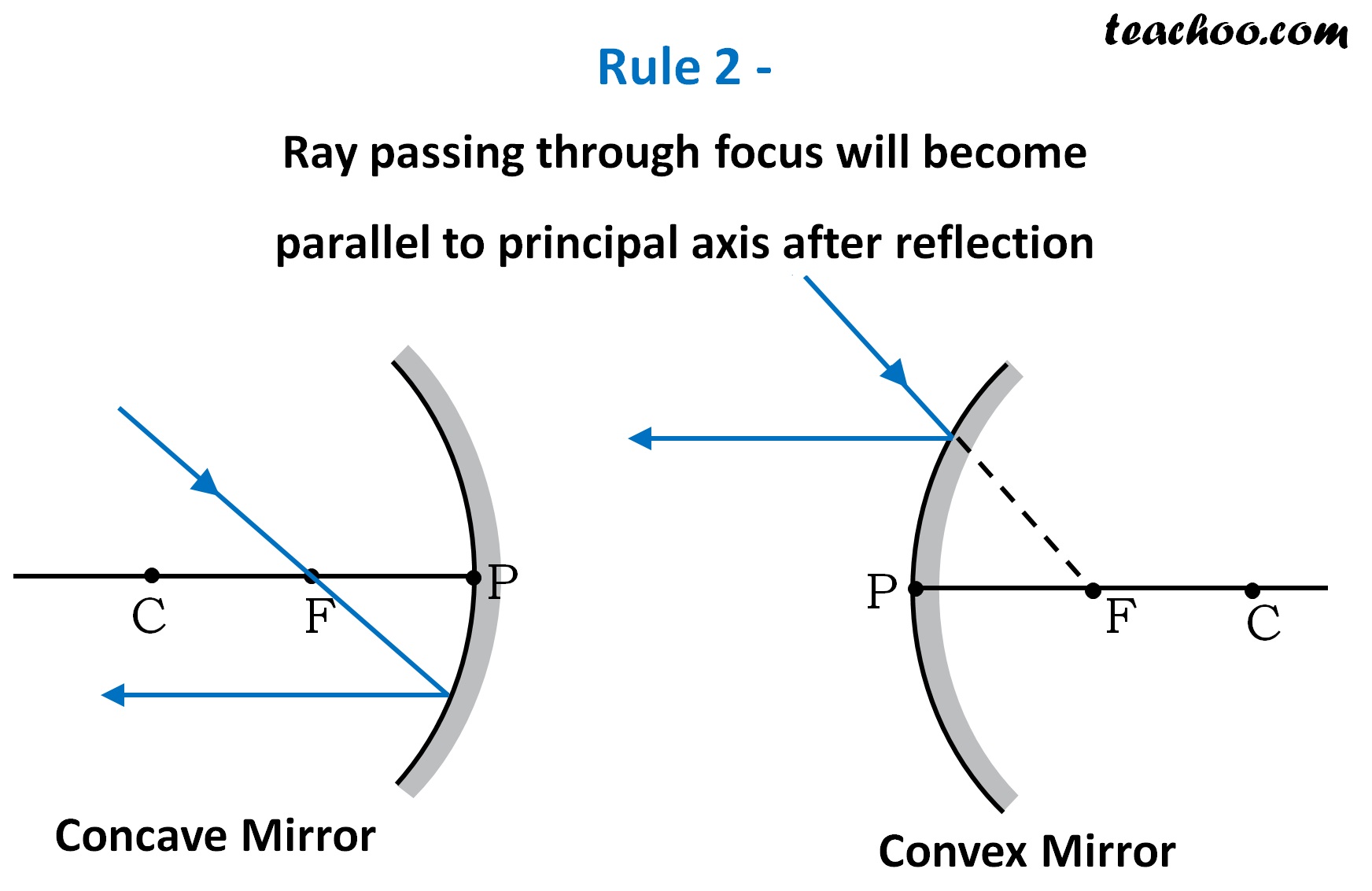
Rules for drawing Ray Diagram in Concave and Convex Mirror Teachoo

Rules for drawing Ray Diagram in Concave and Convex Mirror Teachoo
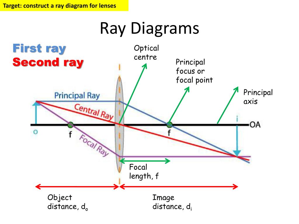
PPT Ray Diagrams PowerPoint Presentation, free download ID6878954
Ray diagrams for convex mirrors

30 Ray Diagram Of Converging Lens Wiring Diagram Database
How To Draw Ray Diagram (POWERPOINT) PDF
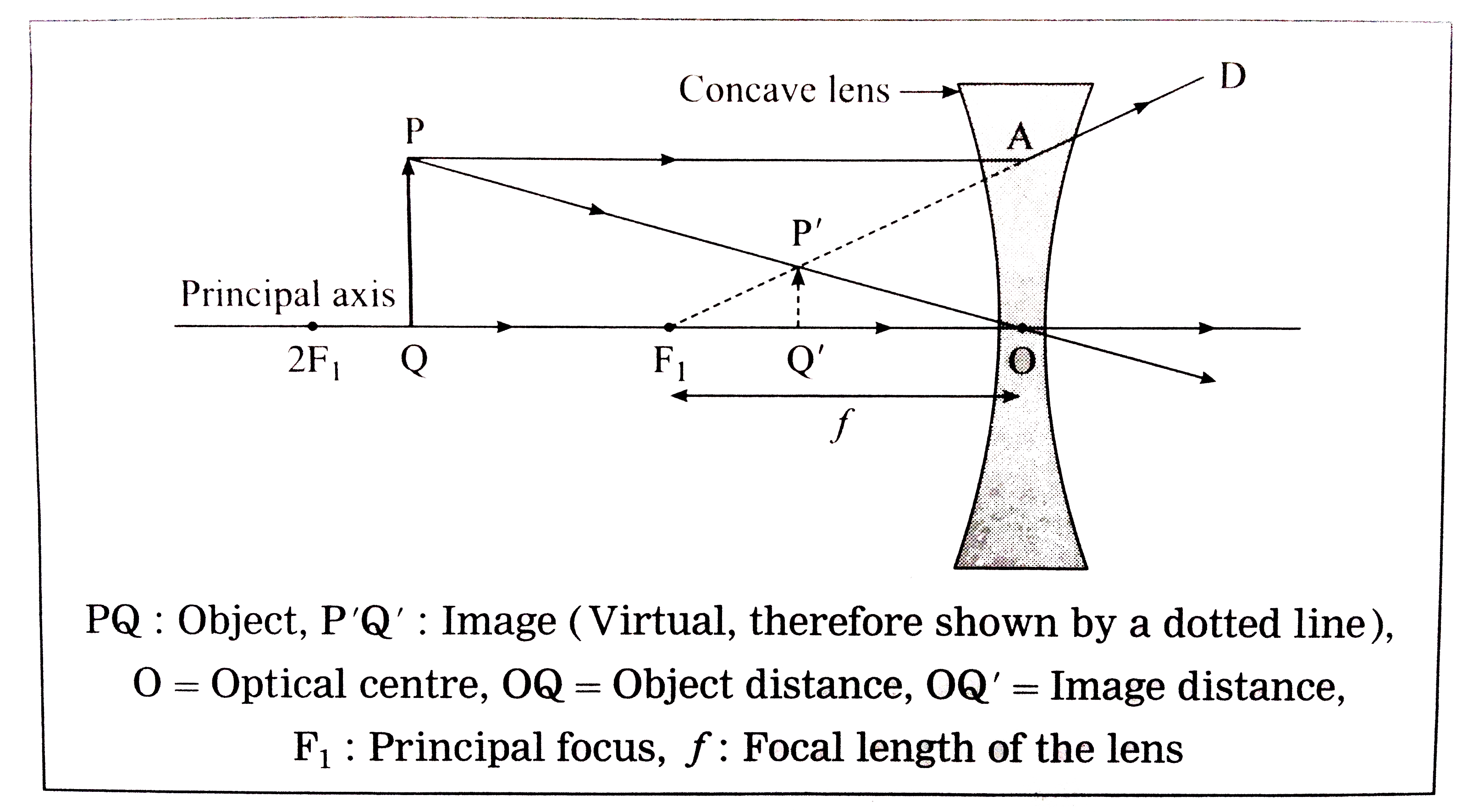
How To Draw Ray Diagrams of all time Don t miss out howtodrawimages1
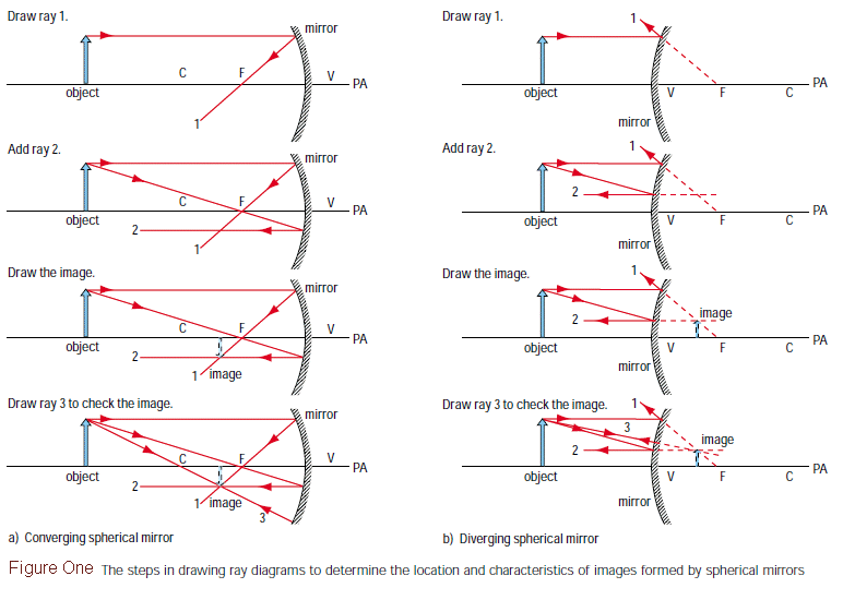
My Physics Webschool Ray Diagram
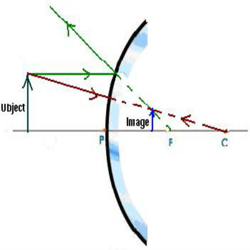
How to Draw a Ray Diagrams for Convex Mirrors

How to draw ray diagrams // Convex lens ray diagrams // Class 10
Use Law Of Reflection To Work Out Incident Rays.
Choose A Point On The Optical Axis, And Label It “A”.
There Are A Few Important Things To Note:
Since Ray Parallel To Principal Axis Passes Through The Focus.
Related Post:
.PNG)
