Drawing Pulley
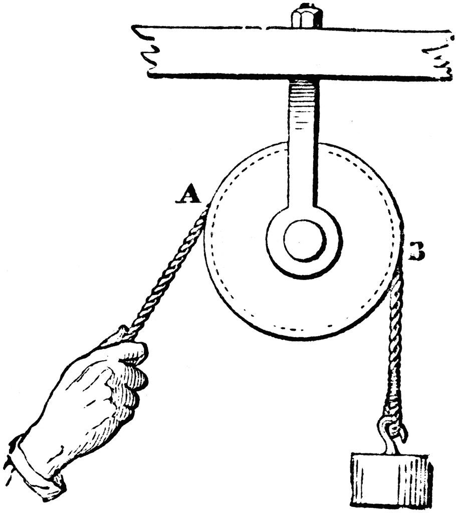
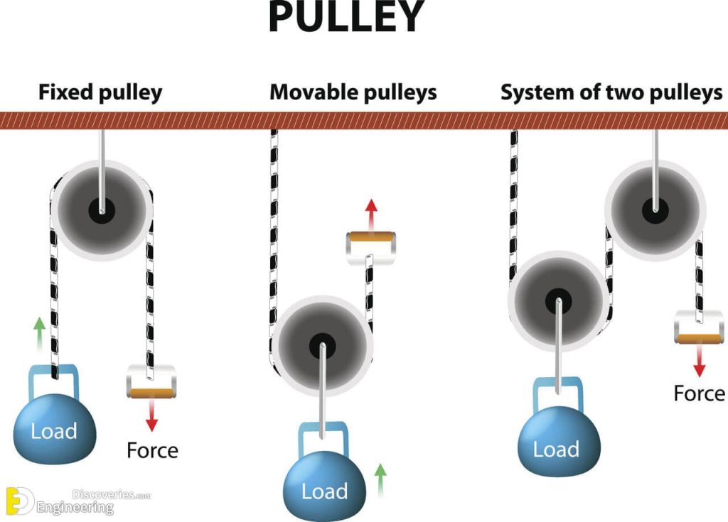
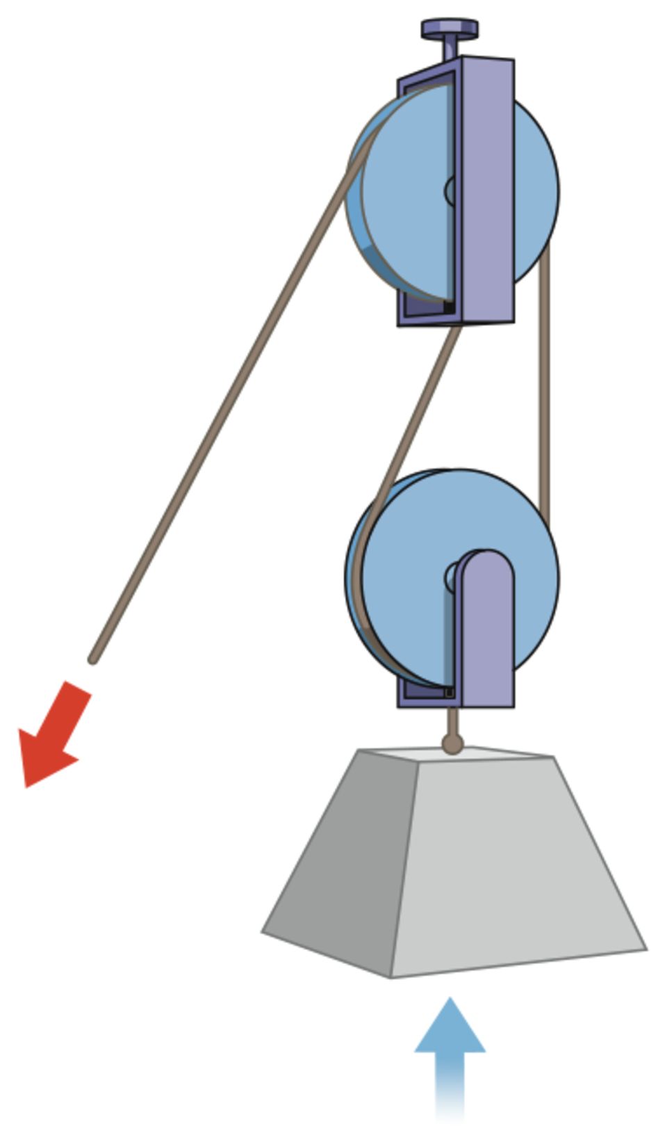
Drawing Pulley - So, as in the picture below, you pull the rope down to lift the weight up. If you want to lift something that weighs 100kg, you have to pull down with a force equivalent to 100kg, which is 1000n (newtons). Web to start making the cad, we start on a side face of the pulley and draw a single construction line running out vertically from the center, and then an arc centered at the middle of the pulley from the other end of the construction line going out an arbitrary length. The pulley wheel is the circular component of the pulley system. A push or a pull on an object; A pulley is used for lifting heavy objects by applying force at one end of the rope. The calculator can be used for metric and imperial units as long as the use of units are consistent. This is the pulley that is being. Join the grabcad community today to gain access and download! The calculator below can be used to calculate effort force in block, tackle or pulley construction. A system of belt pulley drive, drawn using autocad solid models, is shown in fig. Web in your cad software sketch a circle of this diameter. Web if you have a single wheel and a rope, a pulley helps you reverse the direction of your lifting force. Solidworks, step / iges, rendering, february 23rd, 2024. Web this diagram helps us. This is the pulley whose shaft is being driven by something, like a motor, crank, or possibly by another pulley if in a larger system. The figure clearly explains how the belt transmits motion from the driving shaft (may be attached to an. Therefore, the three main parts of a pulley are the wheel, axle, and rope. A pulley is. Web what is a pulley. Web creating a free body diagram for a tension pulley system involves a few simple steps. This is the pulley that is being. A pulley is a type of device that uses physics to lift an object. Not great for lifting things off into the sky. Cad modeling learn pulley solidworks: The capacity to do work. Web if you have a single wheel and a rope, a pulley helps you reverse the direction of your lifting force. A push or a pull on an object; Web #pulleys #adimushow #howtodraw this is an easy drawing of a simple pulley system.this will teach you how to draw parts. Join the grabcad community today to gain access and download! In this example, let’s consider a pulley system with friction. The wheel has a grooved rim that allows a belt or rope to run along it. This is the pulley that is being. Solidworks, step / iges, rendering, february 23rd, 2024. Web a pulley diagram is a visual representation of a system that uses pulleys to transmit motion or lift heavy objects. You have the choice of using the built in drawing tools or to free draw with the collection of movable pieces. Web hi, welcome to athaya drawing!thanks for watching, like, share, comment, and subscribe.how to draw pulley#pulley #pulleydrawing It. Understanding pulley diagrams can help in solving mechanical problems and designing efficient pulley systems. Draw a pulley with h. This is the pulley whose shaft is being driven by something, like a motor, crank, or possibly by another pulley if in a larger system. Solidworks, step / iges, rendering, february 23rd, 2024. Sign in or create account Therefore, the three main parts of a pulley are the wheel, axle, and rope. Cannot lift objects straight (it will tilt to one side) so if you were carrying, say, a big basket of some sort with items inside, the items inside the basket could fall out due to the tilting. A pulley is a wheel on an axle or. It is constructed by looping a rope or a cable around the groove of the wheel. Web hi, welcome to athaya drawing!thanks for watching, like, share, comment, and subscribe.how to draw pulley#pulley #pulleydrawing A pulley is a wheel on an axle or shaft enabling a taut cable or belt passing over the wheel to move and change direction, or transfer. The pulley wheel is the circular component of the pulley system. A system of belt pulley drive, drawn using autocad solid models, is shown in fig. A push or a pull on an object; The natural force of attraction exerted by earth upon objects at or near its surface, tending to draw them toward the center of the body. This. Next, represent the object as a dot or a simple shape, and draw arrows to represent the forces acting on it. Free body diagram of a pulley with friction. This is the pulley that is being. Solidworks, rendering, february 24th, 2024 cable pulley support. Calculate the diameter of your pulley if you were to measure it with a caliper valley to valley by subtracting two times the tooth height of 2.06 mm. Web a pulley diagram is a visual representation of a system that uses pulleys to transmit motion or lift heavy objects. Solidworks, step / iges, rendering, february 23rd, 2024. A push or a pull on an object; Sign in or create account Understanding pulley diagrams can help in solving mechanical problems and designing efficient pulley systems. The capacity to do work. Therefore, the three main parts of a pulley are the wheel, axle, and rope. If you want to lift something that weighs 100kg, you have to pull down with a force equivalent to 100kg, which is 1000n (newtons). Draw a pulley with h. You have the choice of using the built in drawing tools or to free draw with the collection of movable pieces. The wheel has a grooved rim that allows a belt or rope to run along it.
How to draw Pulley YouTube

Work & Simple Machines Tony Marzullo PLN

ASSEMBLY DRAWING Pulley Assembly Part 1/2 YouTube

How to draw Pulley YouTube

How to draw a simple pulley system Setp by step drawing tutorial YouTube

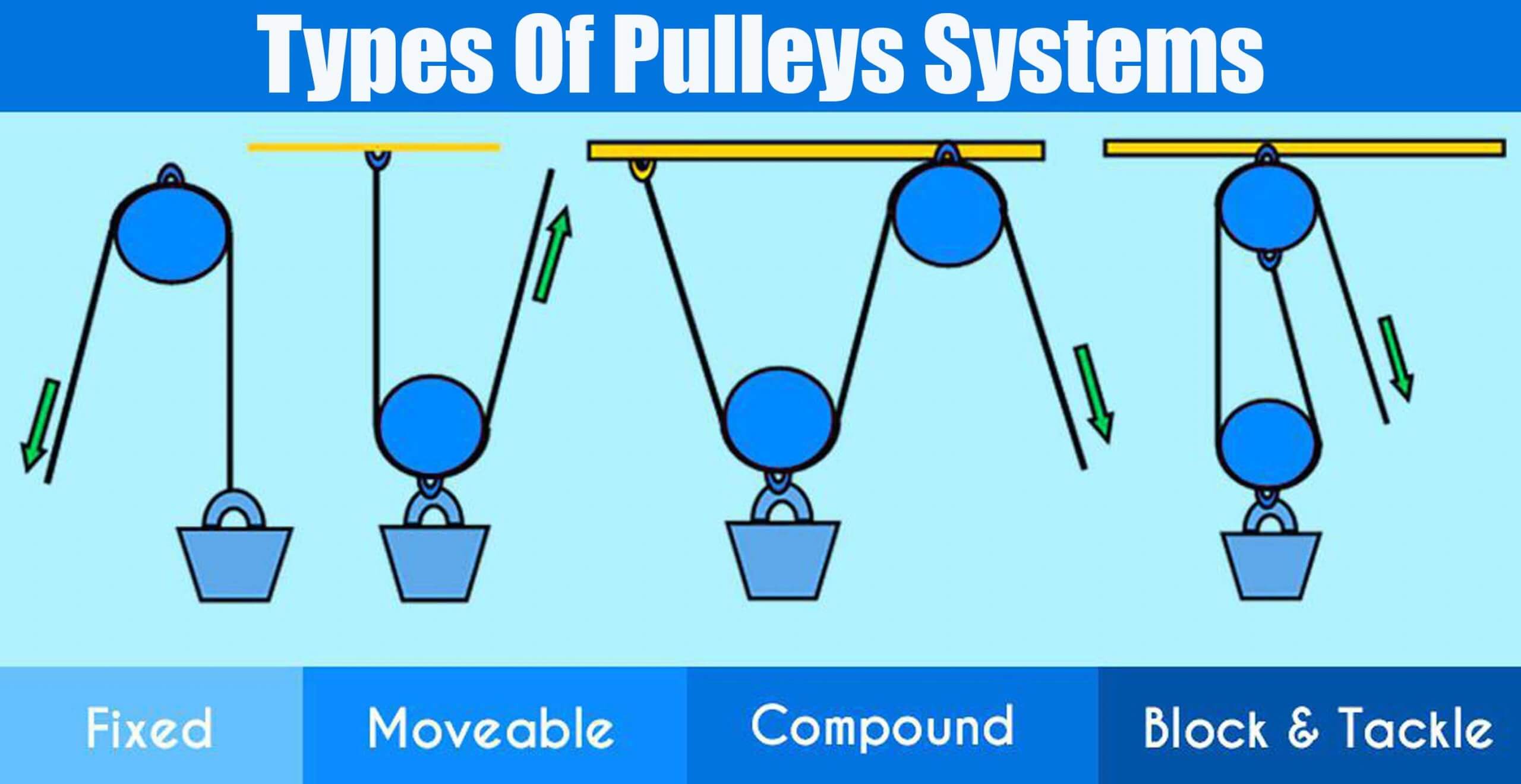
Types Of Pulleys Systems Engineering Discoveries

Types Of Pulleys Systems Engineering Discoveries

How to draw simple machines. Pulleys in isometric view 3D

Pulley System for Kids (Simple Machine Science) • Kids Activities Blog

Types Of Pulley Definition, Uses, Diagram, Examples, Advantages
The Calculator Can Be Used For Metric And Imperial Units As Long As The Use Of Units Are Consistent.
Use This Worksheet To Create Diagrams Having To Do With Various Mechanics Situations.
Web To Start Making The Cad, We Start On A Side Face Of The Pulley And Draw A Single Construction Line Running Out Vertically From The Center, And Then An Arc Centered At The Middle Of The Pulley From The Other End Of The Construction Line Going Out An Arbitrary Length.
Web The Transmission Ratios Of Torques And Speed At The Driving And Driven Pulleys Are Ascertained By The Ratio Of Pulley Diameters.
Related Post: