Each Resistor In The Three Circuits In The Drawing
Each Resistor In The Three Circuits In The Drawing - Each resistor has a value of 10.0 ω. Draw a circuit with resistors in parallel and in series. Web the drawing shows three different resistors in two different circuits. Web the circuit in the drawing contains three identical resistors. There is a power supply for six vaults. By the end of this section, you will be able to: Web two resistors connected in series (r1, r2) are connected to two resistors that are connected in parallel (r3, r4). {eq}\frac {1} {r_ {eq}} = \frac {1}. Web figure 19.16 the left circuit diagram shows three resistors in parallel. Web {eq}r_ {eq} = r_1 + r_2 + r_3 +. {eq}\frac {1} {r_ {eq}} = \frac {1}. Web the drawing shows three different resistors in two different circuits. Draw a circuit with resistors in parallel and in series. Calculate the voltage drop of a. Determine the equivalent resistance between the points a and b. For example, an automobile’s headlights,. Web it has a battery and it has three resistors, and a configuration that's called a series resistor configuration. Series resistors is a familiar pattern, and what you're looking for is. Draw a circuit with resistors in parallel and in series. Ssm the circuit in the drawing contains five identical resistors. Web the circuit in the drawing contains three identical resistors. The battery has a voltage of v = 21 v, and the resistors have resistances of r1 = 50.0 ω, r2 = 25.0 ω and. Web the drawing shows three different resistors in two different circuits. Calculate the voltage drop of a. Web two resistors connected in series (r1, r2). Web the drawing shows three different resistors in two different circuits. Web the drawing shows three different resistors in two different circuits. The values for r and v are 8 ω and 6. The currents that flow through each branch. Web resistors are in parallel when each resistor is connected directly to the voltage source by connecting wires having negligible. For example, an automobile’s headlights,. Series resistors is a familiar pattern, and what you're looking for is. Ssm the circuit in the drawing contains five identical resistors. Web figure 19.16 the left circuit diagram shows three resistors in parallel. Web the circuit in the drawing contains three identical resistors. The battery has a voltage of v = 24.0 v, and the resistors have values of r 1 = 50.0 ω, r 2 =. What is the resistance r of each resistor?. Web the circuit in the drawing contains three identical resistors. Use circuit symbols to construct schematic diagrams for the following circuits: The current from the power supply. The current from the power supply. Web current through each resistor can be found using ohm’s law i = v / r, i = v / r, where the voltage is constant across each resistor. Web the circuit in the drawing contains three identical resistors. Use circuit symbols to construct schematic diagrams for the following circuits: There is a power. Web current through each resistor can be found using ohm’s law i = v / r, i = v / r, where the voltage is constant across each resistor. Consider the equivalent resistance between the two points $a$ and $b, b$ and $c,$ and $a$ and c. Use circuit symbols to construct schematic diagrams for the following circuits: The values. Determine the equivalent resistance between the points a and b. Web the drawing shows three different resistors in two different circuits. Each resistor has a value of 10.0 ω. The voltage v of the battery is applied across all three resistors. Web two resistors connected in series (r1, r2) are connected to two resistors that are connected in parallel (r3,. Ssm the circuit in the drawing contains five identical resistors. Web in this circuit, points b and e each have three wires connected, making them junctions. The values for r and vare 802. Web two resistors connected in series (r1, r2) are connected to two resistors that are connected in parallel (r3, r4). Web {eq}r_ {eq} = r_1 + r_2. Each resistor thus has the full voltage of. Determine the following quantities for each of the two circuits shown below…. For example, an automobile’s headlights,. Use circuit symbols to construct schematic diagrams for the following circuits: The values for r and v are 8 ω and 6. Web resistors are in parallel when each resistor is connected directly to the voltage source by connecting wires having negligible resistance. Calculate the voltage drop of a. The voltage v of the battery is applied across all three resistors. The values for r r and v v are. Web each resistor in the three circuits in the drawing has the same resistance r, r, and the batteries have the same voltage v. Consider the equivalent resistance between the two points $a$ and $b, b$ and $c,$ and $a$ and c. Web the circuit in the drawing contains three identical resistors. Web the circuit in the drawing contains three identical resistors. Web current through each resistor can be found using ohm’s law i = v / r, i = v / r, where the voltage is constant across each resistor. The battery has a voltage of v = 21 v, and the resistors have resistances of r1 = 50.0 ω, r2 = 25.0 ω and. Web two resistors connected in series (r1, r2) are connected to two resistors that are connected in parallel (r3, r4).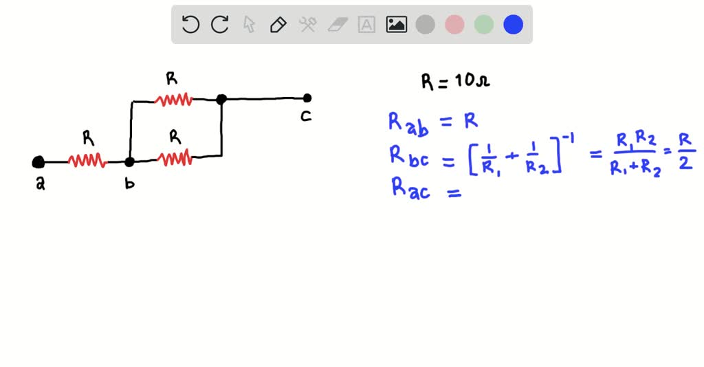
SOLVEDConcept Question The circuit in the drawing contains three
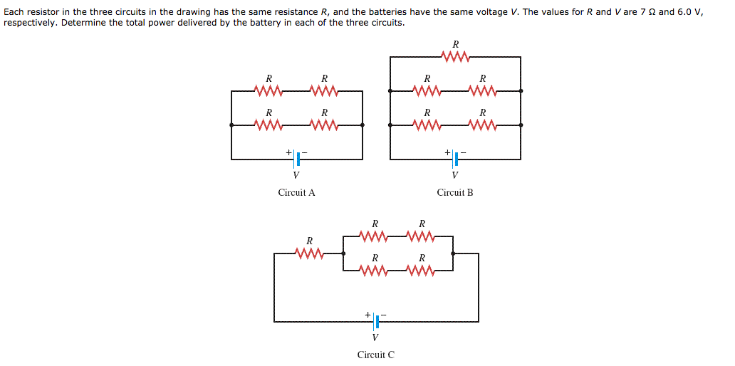
Solved Each resistor in the three circuits in the drawing

Question 3 Each resistor in the three circuits in the drawing has the
[Solved] Current Attempt in Progress Each resistor in the
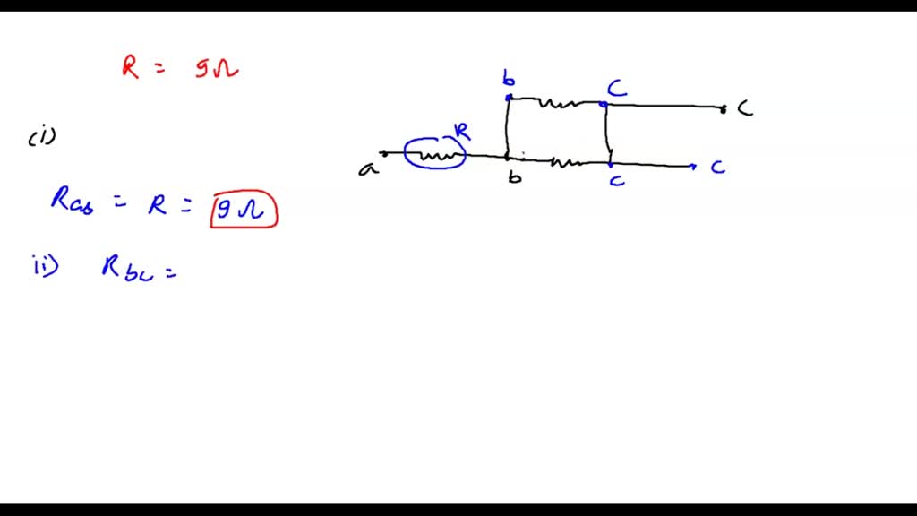
SOLVED The circuit in the drawing contains three identical resistors

Each resistor in the three circuits in the drawing has the same
Solved Each resistor in the three circuits in the drawing

Three resistors having resistances r1, r2 and r3 are connected as shown
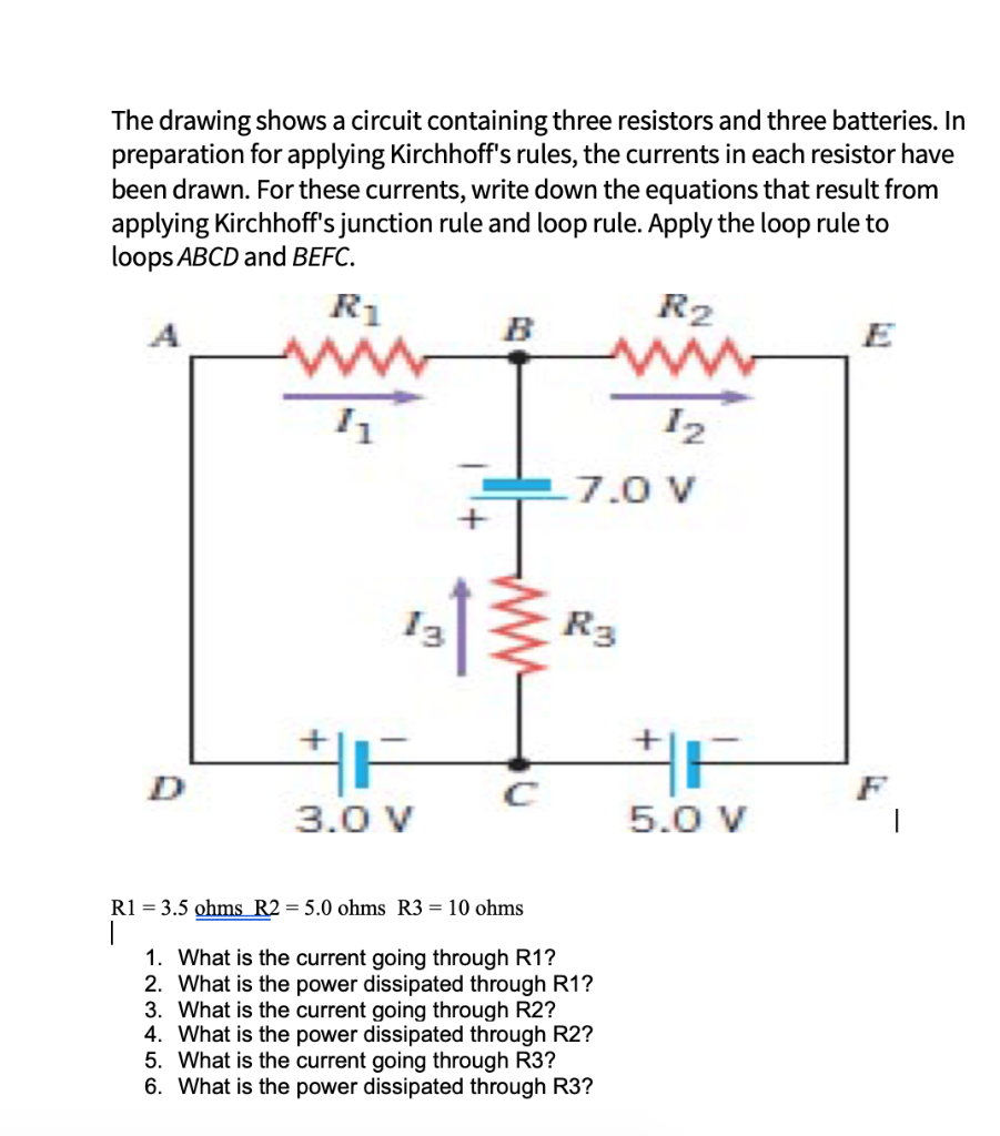
Solved The drawing shows a circuit containing three
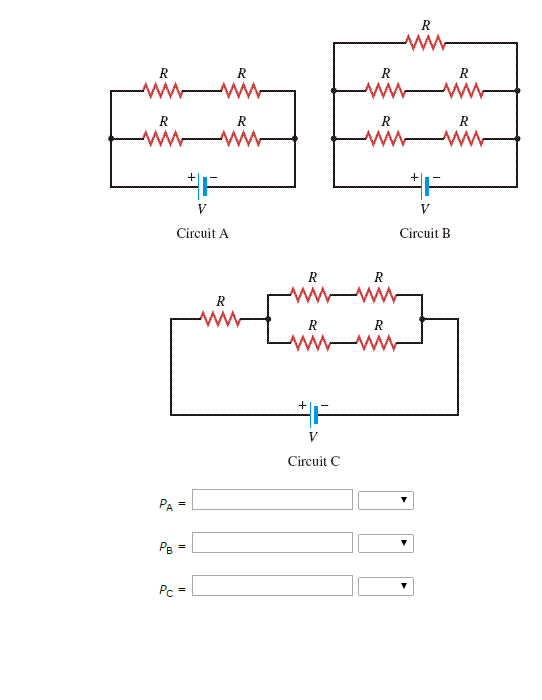
(Get Answer) Each resistor in the three circuits in the drawing has
Web Figure 19.16 The Left Circuit Diagram Shows Three Resistors In Parallel.
There Is A Power Supply For Six Vaults.
Web {Eq}R_ {Eq} = R_1 + R_2 + R_3 +.
A Single Cell, Light Bulb And Switch Are Placed Together In A Circuit Such That The Switch Can.
Related Post:
![[Solved] Current Attempt in Progress Each resistor in the](https://media.cheggcdn.com/media/536/536d777f-59c7-44d5-8c91-4ccf0edd8b58/phpa7hbwH)
