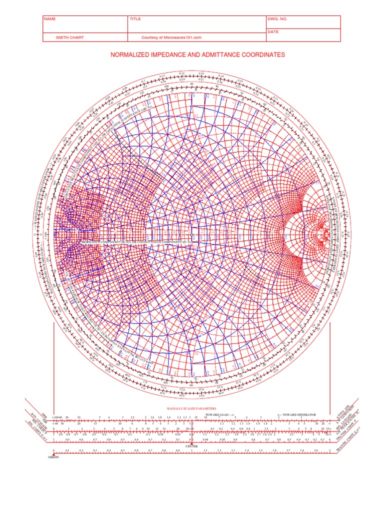
High Resolution Smith Chart
High Resolution Smith Chart - As one of the most important microwave engineering tools, smith chart has been widely used by microwave engineers worldwide. “ impedance matching ” the interactive smith chart enables users to navigate their way around a smith chart, using simple discrete element impedance. Web rf engineering basic concepts: Web the complete smith chart. Web size of this png preview of this svg file: Web 0.1 0.1 0.1 0.2 0.2 0.2 0.3 0.3 0.3 0.4 0.4 0.4 0.5 0.5 0.5 0.6 0.6 0.6 0.7 0.7 0.7 0.8 0.8 0.8 0.9 0.9 0.9 1.0 1.0 1.0 1.2 1.2 1.2 1.4 1.4 1.4 1.6 1.6 1.6 1.8 1.8 1. Navigation in the smith chart. 240 × 240 pixels | 480 × 480 pixels | 768 × 768 pixels | 1,024 × 1,024 pixels | 2,048 × 2,048 pixels |. Web smith chart name title courtesy of microwaves101.com dwg. Date normalized impedance and admittance coordinates r v e i t i c a p a. Date normalized impedance and admittance coordinates r v e i t i c a p a. 35 70 0.34 60 30. Web 0.1 0.1 0.1 0.2 0.2 0.2 0.3 0.3 0.3 0.4 0.4 0.4 0.5 0.5 0.5 0.6 0.6 0.6 0.7 0.7 0.7 0.8 0.8 0.8 0.9 0.9 0.9 1.0 1.0 1.0 1.2 1.2 1.2 1.4 1.4 1.4 1.6 1.6. The smith chart is used to display an actual. Web the complete smith chart. Web smith chart name title courtesy of microwaves101.com dwg. Web rf engineering basic concepts: Web the benefits of the smith chart. The smith chart was invented by phillip smith in 1939 in order to provide an. Web the smith chart is a graphical tool used extensively for wired and wireless design at rf frequencies. Web size of this png preview of this svg file: Web this free online interactive smith chart tool is a calculator which can help you design matching. “ impedance matching ” the interactive smith chart enables users to navigate their way around a smith chart, using simple discrete element impedance. Web the smith chart is a graphical tool used extensively for wired and wireless design at rf frequencies. Web 0.1 0.1 0.1 0.2 0.2 0.2 0.3 0.3 0.3 0.4 0.4 0.4 0.5 0.5 0.5 0.6 0.6 0.6. The smith chart is a very valuable and important tool that. Web definition of the smith chart. Resistance component (r/zo), or conductance component (g/yo) radially scaled parameters toward. Web the smith chart is a fantastic tool for visualizing the impedance of a transmission line and antenna system as a function of frequency. “ impedance matching ” the interactive smith chart. Web size of this png preview of this svg file: 35 70 0.34 60 30. Web the smith chart is a fantastic tool for visualizing the impedance of a transmission line and antenna system as a function of frequency. Visit to learn about our other electrical engineering tools & resources. At first glance, the standard, fully detailed smith chart may. Web this free online interactive smith chart tool is a calculator which can help you design matching networks and obtain maximum power transfer between your source and load. Thus, we can locate the impedance z = 6 +. Web size of this png preview of this svg file: Web various types of smith chart forms are available from arrl hq.. Web various types of smith chart forms are available from arrl hq. The smith chart was invented by phillip smith in 1939 in order to provide an. The smith chart is used to display an actual. Navigation in the smith chart. Web the smith chart presents a large amount of information in a confined space and interpretation, such as applying. Web definition of the smith chart. “ impedance matching ” the interactive smith chart enables users to navigate their way around a smith chart, using simple discrete element impedance. Web the smith chart is a graphical tool used extensively for wired and wireless design at rf frequencies. At first glance, the standard, fully detailed smith chart may look like a. Web the smith chart presents a large amount of information in a confined space and interpretation, such as applying appropriate signs, is required to extract values. Web rf engineering basic concepts: The smith chart above shows both the impedance mapping (red) and admittance mapping (blue). As one of the most important microwave engineering tools, smith chart has been widely used. Web definition of the smith chart. At the time of this writing, five 81/ 2 × 11 inch smith chart forms are available for $2. Web rf engineering basic concepts: Web the smith chart is a fantastic tool for visualizing the impedance of a transmission line and antenna system as a function of frequency. Date normalized impedance and admittance coordinates r v e i t i c a p a. The smith chart above shows both the impedance mapping (red) and admittance mapping (blue). Web the complete smith chart. Web the complete smith chart. Web revised july 9, 2014. Visit to learn about our other electrical engineering tools & resources. “ impedance matching ” the interactive smith chart enables users to navigate their way around a smith chart, using simple discrete element impedance. Web the benefits of the smith chart. The smith chart was invented by phillip smith in 1939 in order to provide an. Web the smith chart presents a large amount of information in a confined space and interpretation, such as applying appropriate signs, is required to extract values. Web download free, online, and printable smith chart graph paper (pdf) from eeweb. Web the smith chart presents a large amount of information in a confined space and interpretation, such as applying appropriate signs, is required to extract values.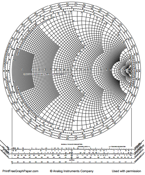
Printable Smith Chart
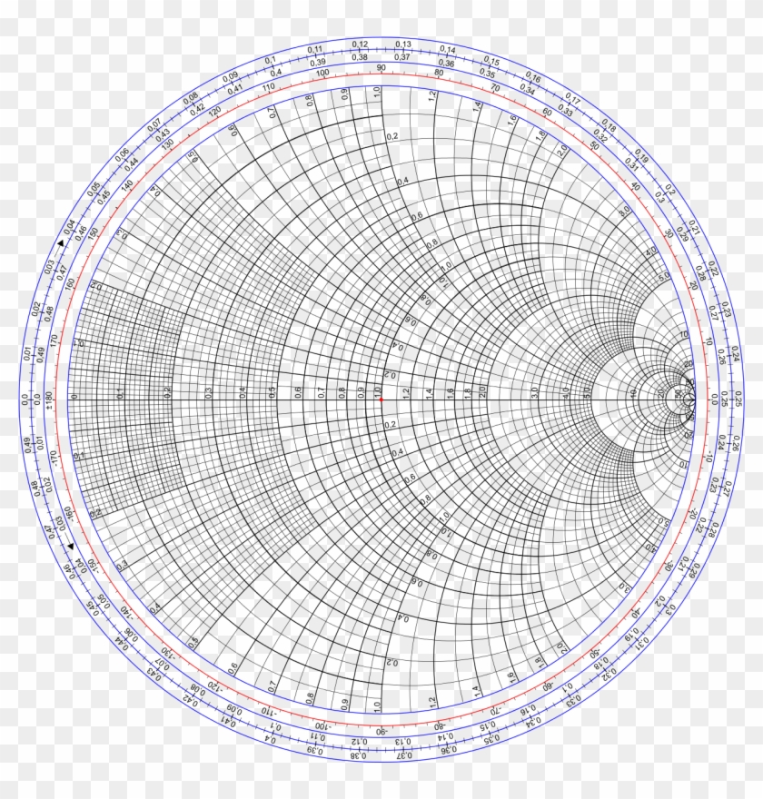
Printable Smith Chart Printable Word Searches

Smith Chart Graph Paper to download and print Electronic Products

Typical Smith chart. With permission of Spread Spectrum Scene
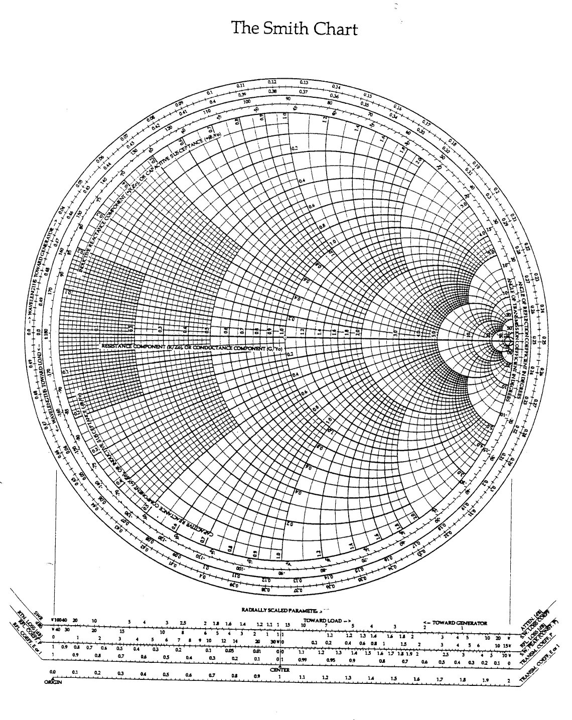
What is a Smith Chart?

The Smith Chart A Vital Graphical Tool DigiKey

The Smith Chart. Infographics and Data Visualizations Pinterest
Printable Smith Chart
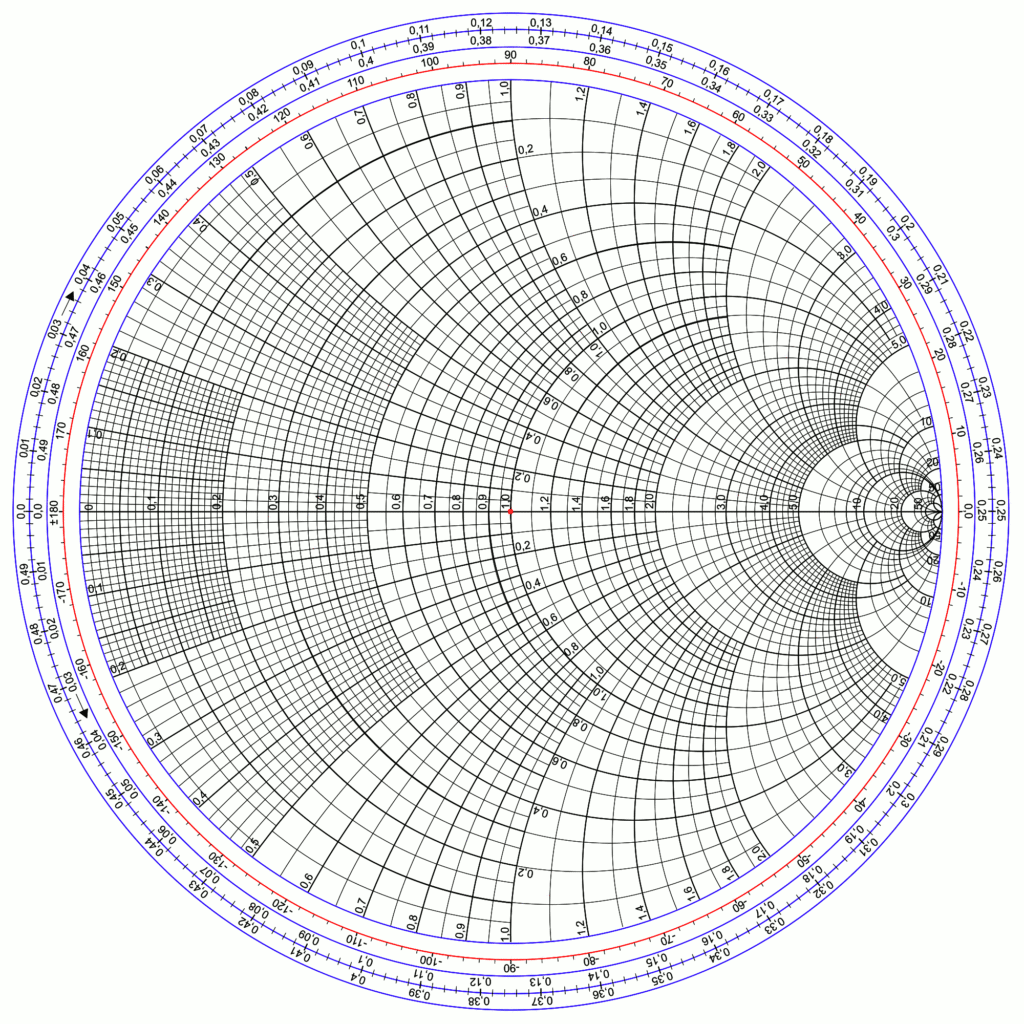
Revisiting the Smith Chart AGC Systems
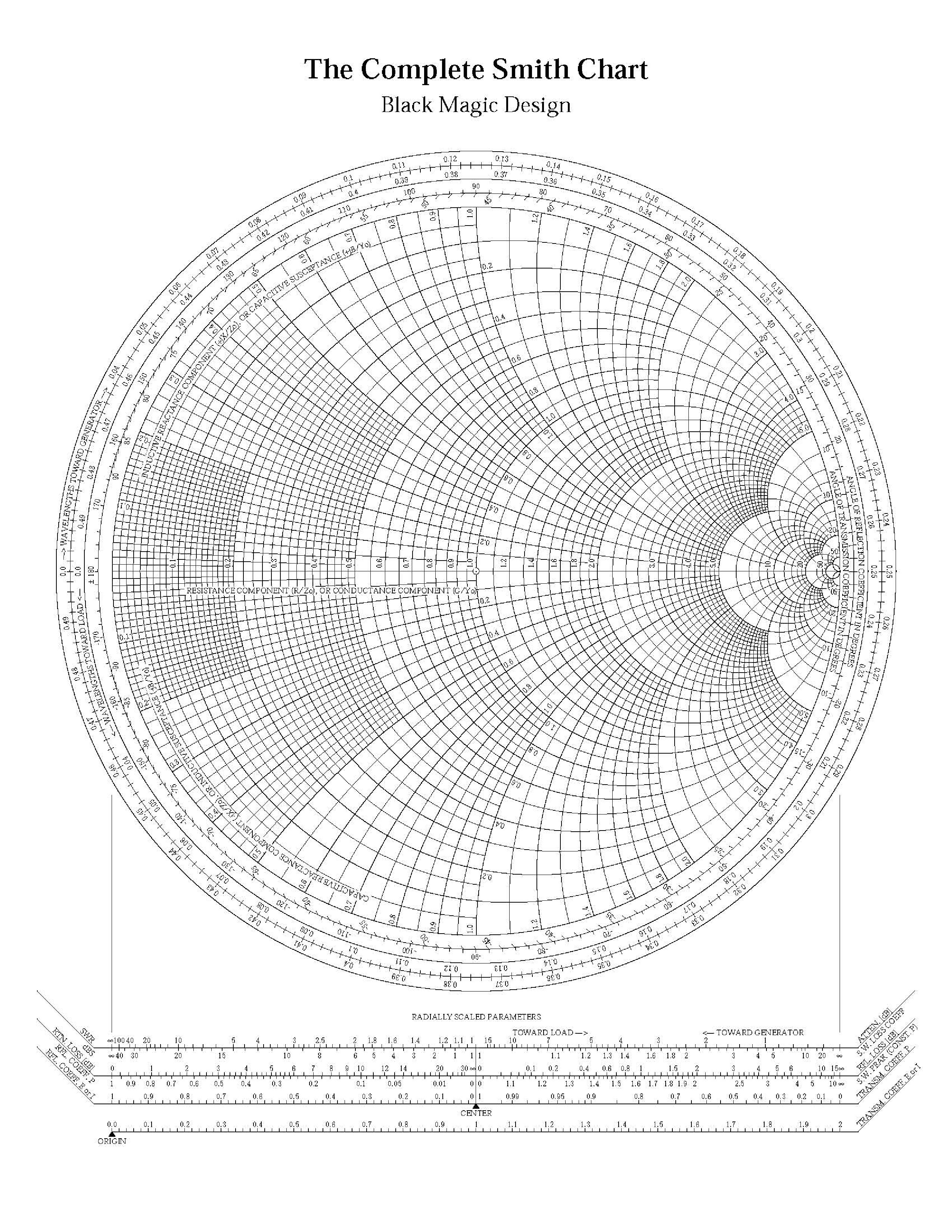
Smith Chart Ximera
Web This Free Online Interactive Smith Chart Tool Is A Calculator Which Can Help You Design Matching Networks And Obtain Maximum Power Transfer Between Your Source And Load.
Navigation In The Smith Chart.
Web The Smith Chart Is A Graphical Tool Used Extensively For Wired And Wireless Design At Rf Frequencies.
35 70 0.34 60 30.
Related Post:
