How To Draw A State Machine Diagram
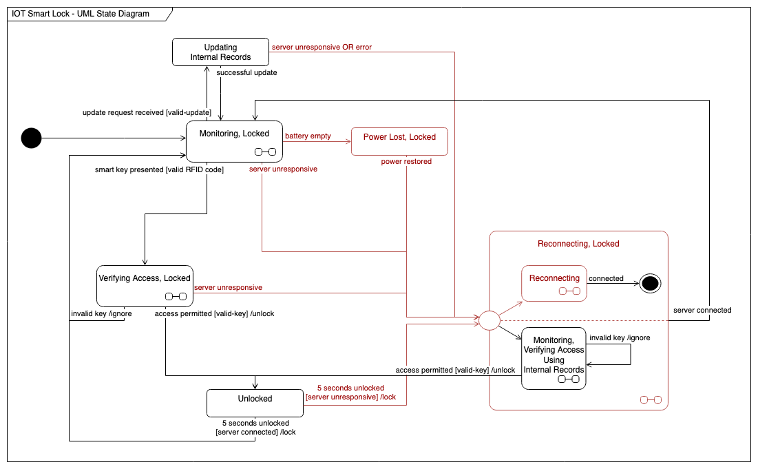
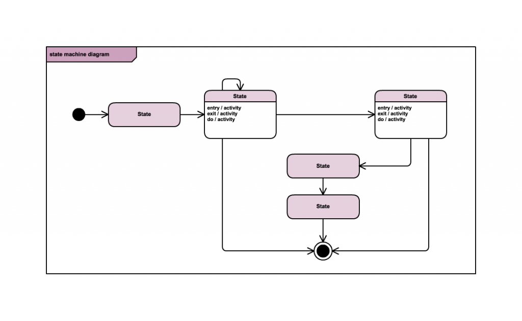
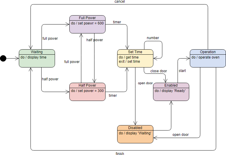
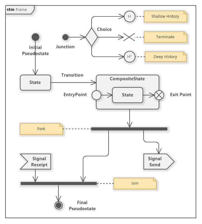
How To Draw A State Machine Diagram - L=1 binary values of states. Web plantuml provides a simple and intuitive syntax to create state machine diagrams. Web a state machine diagram is a behavior that specifies the sequences of states an object goes through during its lifetime in response to events. A state machine diagram is a graph consisting of: Draw directed lines to depict changes from one state to another. “if l=1 at the clock edge, then jump to l=1 l=1 state 01.”. Web ave coders!the behavior of an entity is not only a direct result of the input, but it also depends on its preceding state. These diagrams consist of states, transitions, and optional actions or events associated with each transition. In the new diagram window, select state machine diagram, then click next. Web easily create a visual narrative of a system's behavior. States (simple states or composite states) state transitions connecting the states. L=1 binary values of states. Web a state is a constraint or a situation in the life cycle of an object, in which a constraint holds, the object executes an activity or waits for an event. These terms are often used. The change in one state to another is. They also quickly show which states lead to each other, and what triggers a change of state. If you don’t see it, go to view > task panes. Web enter the plantuml description of your state machines in the textbox, and click apply. All of the possible states of a particular component must be identified before drawing a state machine. Here's a basic example of a plantuml state machine diagram: States are represented with rectangles with rounded corners that are labeled with the name of the state. Web a state machine diagram is a behavior that specifies the sequences of states an object goes through during its lifetime in response to events. After that, click the “new flowchart” button from. Transitions are marked with arrows that flow from one state to another, showing how the states change. In the dialog box, select the either metric units or us units. In this tutorial, we will name the diagram state machine diagram tutorial. Web the state machine diagram is used to portray various states underwent by an object. In the search box,. If you don’t see it, go to view > task panes. Unsynchronized level to user input d q d q l pulse p fsm. Web state diagrams mainly depict states and transitions. For example, turning the example of the composite reconnecting state above into a plantuml text description: These diagrams consist of states, transitions, and optional actions or events associated. Web creating a state machine diagram. A state machines are used to model the behavior of. Web 5 steps to draw state machine diagram. Web a state of an entity is controlled with the help of an event. Unsynchronized level to user input d q d q l pulse p fsm. This state diagram models the behavior of a vending machine that dispenses candy bars and gives change if the user inserts excess amount. It shows the various states that the machine can be in and the transitions that occur when the user interacts with the. A state machine diagram is a graph consisting of: The change in one state to. Web easily create a visual narrative of a system's behavior. A state machine are used to specify the behavior of objects that must respond to asynchronous stimulus or whose current behavior depends on their past. Web sewing machine diagram drawing || how to draw sewing machine || sewing machine labelled diagram#artwithb #howtodraw #pencildrawing #diagram 00:00 intro 00:09. A state is. Web design state machine diagram online. You can use the search bar above to filter results. Web a state is a constraint or a situation in the life cycle of an object, in which a constraint holds, the object executes an activity or waits for an event. A state machine are used to specify the behavior of objects that must. Web develop the state chart diagram for the vending machine. Web a state diagram is used to represent the condition of the system or part of the system at finite instances of time. State transition diagram is a useful fsm representation and design aid: Web state diagrams mainly depict states and transitions. Use rectangles for states, arrows for transitions, and. Web a state of an entity is controlled with the help of an event. The article then presents a more detailed. The primary focus of the state machine diagram is to depict the states of a. Using your chosen tool, draw the state diagram by representing each state as a box or circle and connecting them with arrows to indicate transitions. These terms are often used. After signing up, open a blank document and enable the uml shape libraries. Web state diagrams have been used in programming to describe the various possible states that a system can be in for decades. Web design state machine diagram online. Smart shapes and connectors, shape search, and easy styling options to quickly and easily create all types of uml diagrams. These diagrams consist of states, transitions, and optional actions or events associated with each transition. Repeat the process until you complete. Here's a basic example of a plantuml state machine diagram: A state machines are used to model the behavior of. Web the state machine diagram is used to portray various states underwent by an object. Behavioral diagram and it represents the behavior using finite state transitions. Web a state machine diagram is a behavior that specifies the sequences of states an object goes through during its lifetime in response to events.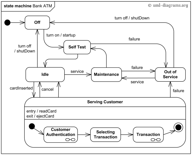
A simple guide to drawing your first state diagram (with examples) Nulab
Blog Draw a UML state machine diagram
A simple guide to drawing your first state diagram (with examples) Cacoo
State Machine Diagram Tutorial
Event driven state machine 101 Adaptive Financial Consulting

MSP430 State Machine project with LCD and 4 user buttons

5 Steps to Draw a State Machine Diagram YouTube
State Machine Diagram Tutorial Lucidchart

compiler construction Drawing Finite State Machine FSM for finding
UML State Machine Diagram Tutorial Software Ideas Modeler
A State Machine Diagram Is A Graph Consisting Of:
Web Easily Create A Visual Narrative Of A System's Behavior.
Below, You Can See Both These Elements At Work In A Basic Diagram For Student Life.
Infinite Canvas To Draw Large, Complex State Machine Diagrams With Minimal Effort.
Related Post:
