How To Draw Nyquist Plot
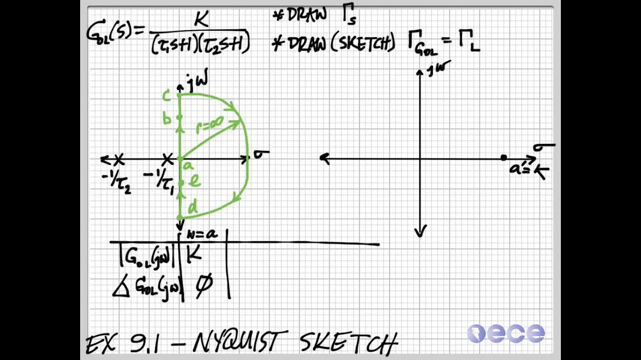
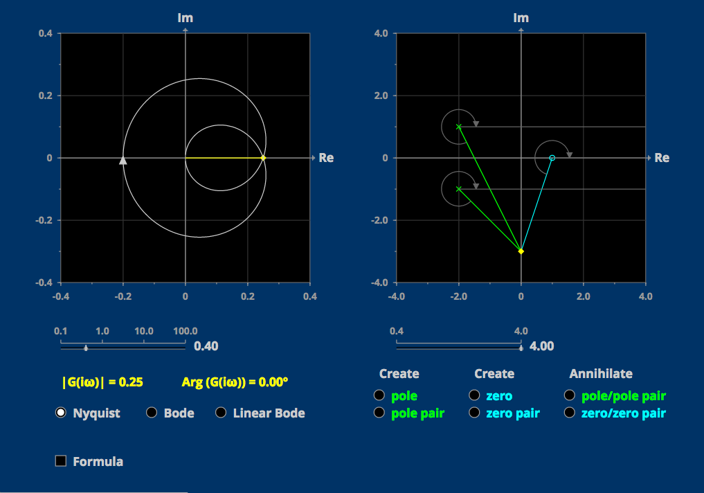
How To Draw Nyquist Plot - • l19e112 control systems lecture 19 ex. Determine the transfer function of the system. Procedure to draw nyquist plot: Nyquist contour engineering funda channel. Recently i wrote a post on stability of linear systems where i introduced the nyquist plot. Web 1 1 + (ωrc)2 1 1 + ( ω r c) 2. Now i want to go into the details of how to draw one without using a bode plot. Hence, should i replace ω ω in the imaginary part with the real part, i.e., im(ω) = −re(ω) × rc 1 + (re(ω)rc)2 i m ( ω) = − r e ( ω) × r c 1 + ( r e ( ω) r c) 2. When g(s) is placed in a unity feedback loop, is the closed loop system stable or unstable? Nyquist plot example here, nyquist plot example includes three major steps 1. Now i want to go into the details of how to draw one without using a bode plot. In this lecture, you will learn: The nichols chart, the nyquist plot, and the bode plot. Draw and map using nyquist contour. If pole or zero present at s = 0, then varying $\omega$ from 0+ to infinity for drawing polar plot. A nyquist plot can be drawn using the following steps: Nyquist plot example here, nyquist plot example includes three major steps 1. Web in general each example has five sections: Web rules for drawing nyquist plots. How to draw nyquist plots exercise 112: Draw and map using nyquist contour. 15k views 1 year ago control systems lectures. Learn about each method, including their strengths, and why you may choose one over another. 81k views 3 years ago control systems in practice. Follow these rules for plotting the nyquist plots. Web the nyquist plot of a transfer function g(s) is shown in figure 1. 81k views 3 years ago control systems in practice. (a) suppose g has two unstable open loop poles. It is drawn by plotting the complex gain g(iw) for all frequencies w. Nyquist contour engineering funda channel. Web 1 1 + (ωrc)2 1 1 + ( ω r c) 2. It is drawn by plotting the complex gain g(iw) for all frequencies w. Mece3350 control systems lecture 19: Web for example, the following matlab commands produce figure \(\pageindex{1}\), a nyquist plot of equation \(\ref{eqn:10.7}\) for undamped natural frequency \(\omega_{n} = 2\pi\) rad/s and damping ratio \(\zeta=0.2\): Web. Hence, should i replace ω ω in the imaginary part with the real part, i.e., im(ω) = −re(ω) × rc 1 + (re(ω)rc)2 i m ( ω) = − r e ( ω) × r c 1 + ( r e ( ω) r c) 2. Web nyquist plot i given a plant with transfer function g(s) i want to. Explore math with our beautiful, free online graphing calculator. That is, the plot is a curve in the plane. Draw and map using nyquist contour. Nyquist plots a contour comprised of both positive and negative frequencies. Web a generic example of how to sketch a nyquist plot from a transfer functions. Web 4.8k views 3 years ago nyquist stability criterion. Web nyquist plot 1. The amplitude response curves given above are examples of the bode gain plot. Web steps to draw nyquist plot 3. Web #controlengineering #controltheory #mechatronics #machinelearning #robotics #electricalengineering #mechanicalengineering #controltheory it takes a significa. It is drawn by plotting the complex gain g(iw) for all frequencies w. I believe nyquist plots plot the imaginary part of the transfer function with the real part as a variable. In this lecture, you will learn: A nyquist plot can be drawn using the following steps: Procedure to draw nyquist plot: Re g(s) in a new plane, call it c 4 i for closed loop stability, c 4 should encircle ( 1=k;0), p times i. Draw inverse polar plot 3. Follow these rules for plotting the nyquist plots. Web nyquist diagram | desmos. Web the key for sketching the nyquist plot is to focus on the phase and not on the. Recently i wrote a post on stability of linear systems where i introduced the nyquist plot. When g(s) is placed in a unity feedback loop, is the closed loop system stable or unstable? Web there are two bode plots one for gain (or magnitude) and one for phase. Web control systems tutorial: Graph functions, plot points, visualize algebraic equations, add sliders, animate graphs, and more. I believe nyquist plots plot the imaginary part of the transfer function with the real part as a variable. Nyquist plot example here, nyquist plot example includes three major steps 1. Nyquist contour engineering funda channel. Web the nyquist plot of a transfer function g(s) is shown in figure 1. Using the bode plot what happens at r = 1 poles on the imaginary axis. Procedure to draw nyquist plot: Learn about each method, including their strengths, and why you may choose one over another. Web explore three ways to visualize the frequency response of an lti system: 15k views 1 year ago control systems lectures. In particular, focus on the crossings of the real and imaginary axis, say the phases 0 ∘, 90 ∘, 180 ∘, 270 ∘, etc. Calculate the complex transfer function value by putting s= j ω, where ‘ ω’ is angular frequency and ‘j’ is the imaginary unit.
Drawing Nyquist Plot at Explore collection of

Drawing Nyquist Plot at Explore collection of

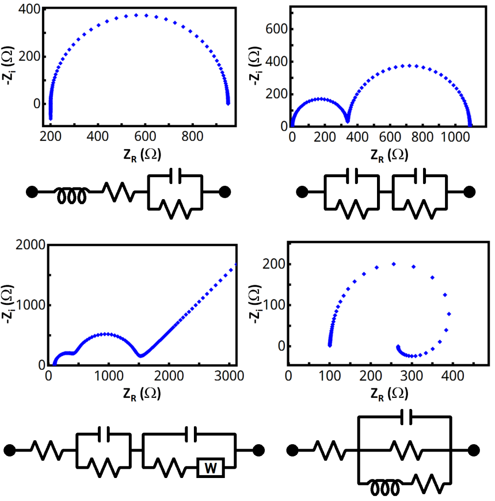
How to Use a Nyquist Plot for AC Analysis Technical Articles

How To Draw Nyquist Plot Warexamination15

How to draw the Nyquist plot Example No. 1 for TypeZero System

How To Draw A Nyquist Diagram » Grantfire

How To Draw Nyquist Plot Warexamination15

Matlab Basics Tutorial13 How to draw Nyquist plot of Transfer

How to draw the Nyquist plot Example No. 2 for TypeOne System Simple

Control Systems Tutorial Sketch Nyquist Plots of Transfer Function by
It Is Drawn By Plotting The Complex Gain G(Iw) For All Frequencies W.
Re G(S) In A New Plane, Call It C 4 I For Closed Loop Stability, C 4 Should Encircle ( 1=K;0), P Times I.
The Nichols Chart, The Nyquist Plot, And The Bode Plot.
Web Nyquist Plot 1.
Related Post: