How To Draw Ray Diagrams
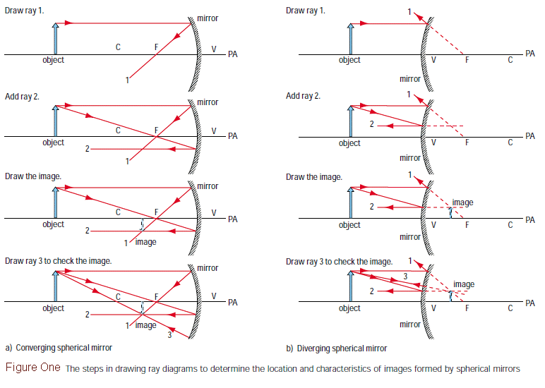
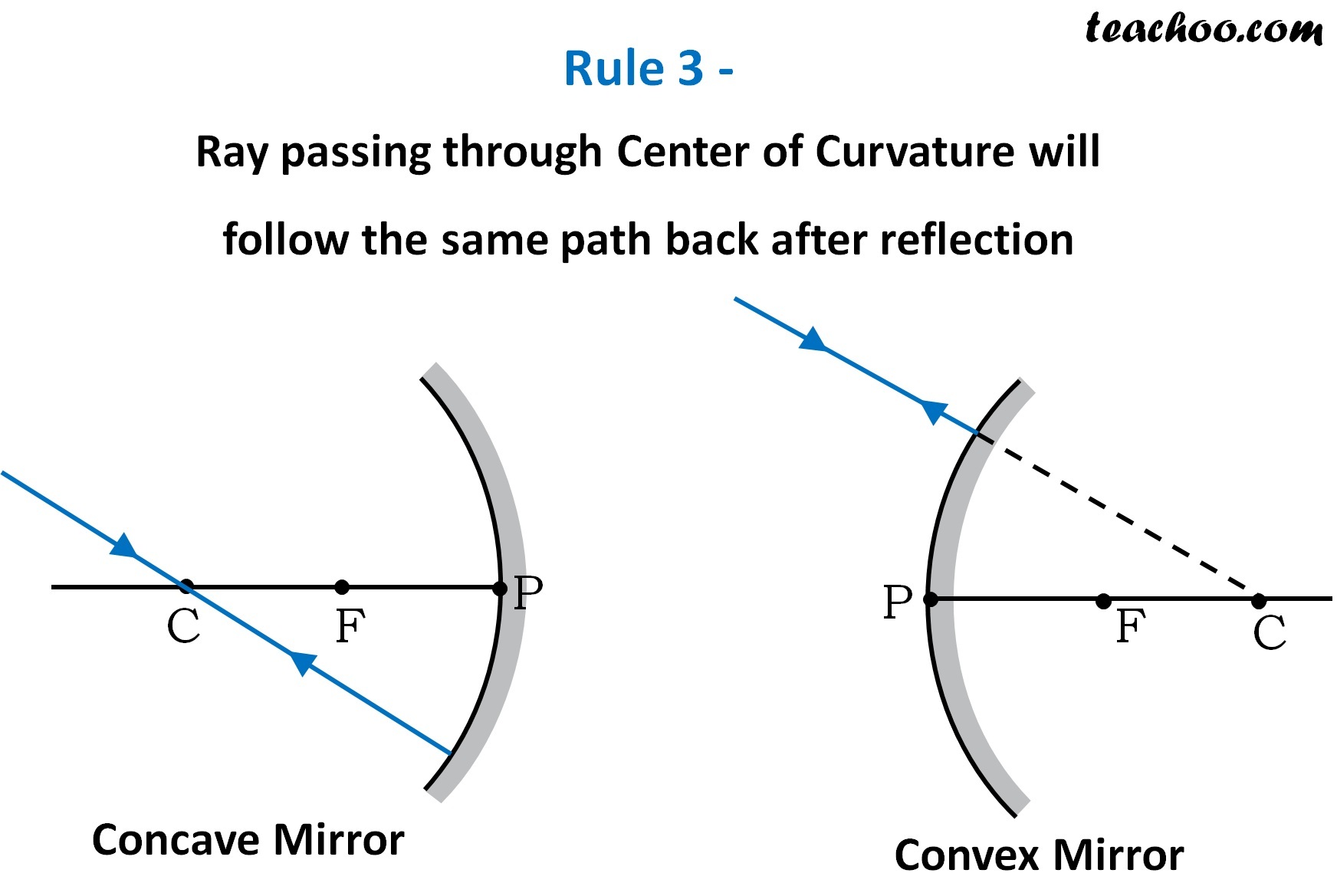
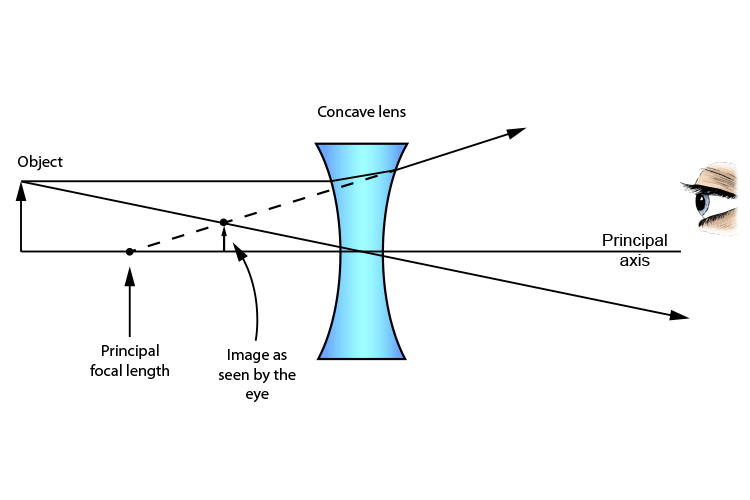
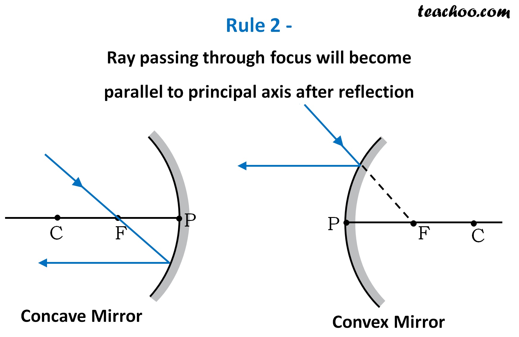
How To Draw Ray Diagrams - Pick one extreme on the image of the object and draw the reflected ray that will travel to the eye as the eye sights at this point. If an object is placed further from the lens than the focal length f then a real image will be formed, and the converging lens ray diagram will be drawn in the following way: Web ray diagrams are employed to comprehend the behaviour of light and better understand image formation. Diagram showing the formation of a real image by a lens. Furthermore, the image will be upright, reduced in size (smaller than the object), and virtual. Label the ends of the optical axis “o” and “p”. Draw a ray from the object to the lens that is parallel to the principal axis. Web an increase in magnetic flux through a coil of 100 turns in 0.1 s is 0.001 wb. This physics video tutorial on optics provides a basic introduction into ray diagrams. Web the location (and nature) of the image can be found by drawing a ray diagram: Pick a point on the top of the object and draw three incident rays traveling towards the lens. Draw a ray which passes. Web in this diagram, five incident rays are drawn along with their corresponding refracted rays. Draw the mirror and the object. Examples are given for converging and diverging lenses and for the cases where the object is. Ray diagrams, reflection, refraction, thin lens equation. Web a ray diagram shows the path of light from an object to mirror to an eye. 992k views 10 years ago optics: Web the drawing ray diagrams for converging lenses video tutorial reviews the three rules of refraction for converging lenses and demonstrates how to use the rules to draw a ray. Ray diagrams, reflection, refraction, thin lens equation. This physics video tutorial on optics provides a basic introduction into ray diagrams. These diagrams use lines with arrows to represent incident and reflected rays, allowing us to trace their paths and interactions with the mirror. Every observer would observe the same image location and every light ray would follow the snell's law. The method for drawing ray diagrams for concave mirror is described below. Label the ends of the optical axis “o” and “p”. Use law of reflection to work out incident rays. Pick a point on the top of the object and draw three incident rays traveling towards the lens. In this keipert labs tutorial, we'll go through how to draw. The image formed by a single lens can be located and sized with three principal rays. Pick one extreme on the image of the object and draw the reflected ray that will travel to the eye as the eye sights at this point. Yet the same method works for drawing a ray diagram for any object location. Let's begin with. Identify and mark the object distance. Draw the mirror and the object. Web there are four steps to the construction of a ray diagram. 260k views 6 years ago. Draw a ray which passes. The maximum induced emf generated in the coil is. For example, you can draw a ray of light parallel to the principal axis which reflects off the mirror and passes through the principal focus (like in this video). Web there are four steps to the construction of a ray diagram. Unlock 50% off on teachoo black. The method for drawing. The maximum induced emf generated in the coil is. This section of lesson 2 details and illustrates the procedure for drawing ray diagrams. Web the organic chemistry tutor. 358k views 8 years ago ap physics 1 videos. Web a ray diagram shows the path of light from an object to mirror to an eye. Web step by step science. Draw the incident ray for light traveling from the corresponding extreme on the object to the mirror. Unlock 50% off on teachoo black. This is often from a source or object to an observer or screen. Web the drawing ray diagrams for converging lenses video tutorial reviews the three rules of refraction for converging lenses. There are a few important things to note: Shows how to draw ray diagrams and. Draw the image of the object. Web ray diagrams are employed to comprehend the behaviour of light and better understand image formation. Web there are some rules which we use to obtain images in a ray diagram. The maximum induced emf generated in the coil is. 595k views 10 years ago optics: Properties of image formed in plane mirror. Web the organic chemistry tutor. Web there are some rules which we use to obtain images in a ray diagram. A ray diagram for a convex mirror shows that the image will be located at a position behind the convex mirror. Critical analysis of ray diagrams. This physics video tutorial on optics provides a basic introduction into ray diagrams. Ray diagrams, reflection, refraction, thin lens equation. Let's begin with the task of drawing a ray diagram to show how suzie will be able to see the image of the green object arrow in the diagram below. We'll go through the do's and don'ts and practice. Every observer would observe the same image location and every light ray would follow the snell's law of refraction. 1.9k views 6 years ago waves and energy. Examples are given for converging and diverging lenses and for the cases where the object is inside and outside the principal focal length. The video lesson answers the following questions: These diagrams use lines with arrows to represent incident and reflected rays, allowing us to trace their paths and interactions with the mirror.
How do we draw ray diagram for plane mirror? YouTube

My Physics Webschool Ray Diagram

How to draw ray diagrams // Convex lens ray diagrams // Class 10

Rules for drawing Ray Diagram in Concave and Convex Mirror Teachoo

Method for drawing ray diagrams Concave lens

How to draw Ray diagrams ? class 10 physics LIGHT chapter made
How To Draw Ray Diagram (POWERPOINT) PDF

Rules for drawing Ray Diagram in Convex and Concave Lens Teachoo

Rules for drawing Ray Diagram in Concave and Convex Mirror Teachoo

Rules for drawing Ray Diagram in Convex and Concave Lens Teachoo
358K Views 8 Years Ago Ap Physics 1 Videos.
992K Views 10 Years Ago Optics:
Web Ray Diagrams Are Employed To Comprehend The Behaviour Of Light And Better Understand Image Formation.
If An Object Is Placed Further From The Lens Than The Focal Length F Then A Real Image Will Be Formed, And The Converging Lens Ray Diagram Will Be Drawn In The Following Way:
Related Post:
