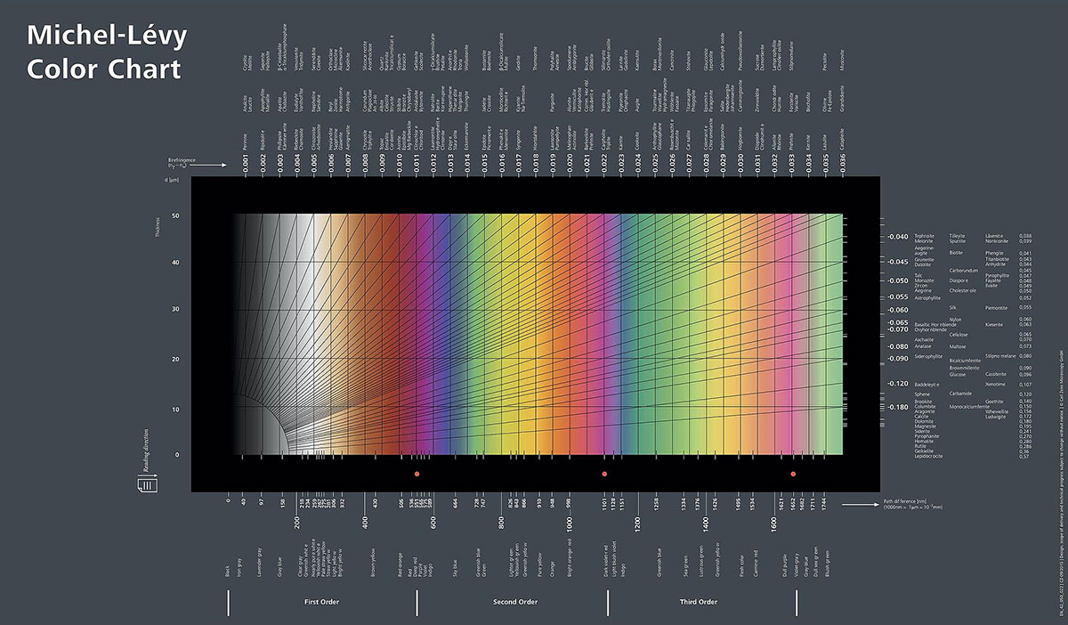
Michel Levy Chart
Michel Levy Chart - Several examples will illustrate this: Department of materials science &. Geomaterials under the microscope \(2013\) 4. The colours are produced by the diff… Suppose a cylindrical synthetic iber 15 μm in diameter shows a maximum interference color Once the appropriate color has been located, the nearest vertical line along the interference color is followed to the nearest horizontal line representing the known thickness. Get access to the full version of this article. From rendering to image colour correction. Interference colours viewed through a quartz wedge, increasing in thickness from left to right, as viewed between crossed polars. From rendering to image colour correction. Get access to the full version of this article. Web the aim of this study is to produce a birefringence colour chart that presents the interference colours as they are observed in the microscope by using the original light interference equations to produce the spectral colours, and then transform them into human vision and device colours that can be viewed. From rendering to image colour correction. Web the aim of this study is to produce a birefringence colour chart that presents the interference colours as they are observed in the microscope by using the original light interference equations to produce the spectral colours, and then transform them into human vision and device colours that can be viewed on a computer. Department of materials science &. Web when illuminated with white (polarized) light, birefringent specimens produce circular distributions of interference colors (figure 2), with the inner circles, called isochromes, consisting of increasingly lower order colors (see the. Interference colours viewed through a quartz wedge, increasing in thickness from left to right, as viewed between crossed polars. From rendering to image colour. The colours are produced by the diff… Web when illuminated with white (polarized) light, birefringent specimens produce circular distributions of interference colors (figure 2), with the inner circles, called isochromes, consisting of increasingly lower order colors (see the. From rendering to image colour correction. Suppose a cylindrical synthetic iber 15 μm in diameter shows a maximum interference color Department of. From rendering to image colour correction. Get access to the full version of this article. Web when illuminated with white (polarized) light, birefringent specimens produce circular distributions of interference colors (figure 2), with the inner circles, called isochromes, consisting of increasingly lower order colors (see the. A chart of standard colours used in measuring birefringence. Interference colours viewed through a. Interference colours viewed through a quartz wedge, increasing in thickness from left to right, as viewed between crossed polars. Once the appropriate color has been located, the nearest vertical line along the interference color is followed to the nearest horizontal line representing the known thickness. Web when illuminated with white (polarized) light, birefringent specimens produce circular distributions of interference colors. Get access to the full version of this article. Web when illuminated with white (polarized) light, birefringent specimens produce circular distributions of interference colors (figure 2), with the inner circles, called isochromes, consisting of increasingly lower order colors (see the. Geomaterials under the microscope \(2013\) 4. Interference colours viewed through a quartz wedge, increasing in thickness from left to right,. The colours are produced by the diff… Get access to the full version of this article. Suppose a cylindrical synthetic iber 15 μm in diameter shows a maximum interference color Once the appropriate color has been located, the nearest vertical line along the interference color is followed to the nearest horizontal line representing the known thickness. From rendering to image. Interference colours viewed through a quartz wedge, increasing in thickness from left to right, as viewed between crossed polars. Once the appropriate color has been located, the nearest vertical line along the interference color is followed to the nearest horizontal line representing the known thickness. From rendering to image colour correction. Department of materials science &. Web the aim of. Suppose a cylindrical synthetic iber 15 μm in diameter shows a maximum interference color Interference colours viewed through a quartz wedge, increasing in thickness from left to right, as viewed between crossed polars. Get access to the full version of this article. Web the aim of this study is to produce a birefringence colour chart that presents the interference colours. The colours are produced by the diff… Get access to the full version of this article. Web the aim of this study is to produce a birefringence colour chart that presents the interference colours as they are observed in the microscope by using the original light interference equations to produce the spectral colours, and then transform them into human vision and device colours that can be viewed on a computer screen. From rendering to image colour correction. Web when illuminated with white (polarized) light, birefringent specimens produce circular distributions of interference colors (figure 2), with the inner circles, called isochromes, consisting of increasingly lower order colors (see the. Geomaterials under the microscope \(2013\) 4. From rendering to image colour correction. A chart of standard colours used in measuring birefringence. Several examples will illustrate this: Interference colours viewed through a quartz wedge, increasing in thickness from left to right, as viewed between crossed polars.
A REVISED MICHEL LéVY INTERFERENCE COLOR CHART BASED ON FIRST

PPT Optical Mineralogy PowerPoint Presentation, free download ID

Birefringence. An interactive Michel Lévy color chart app for Android

GeoClick reading the Michel Levy Color chart

(PDF) A revised MichelLévy interference colour chart based on first

The Petrographer MichelLévy nomogramm

Microscope slides for rock identification
Memahami Warna Interferensi dan Michel Lévy Chart

Figure 1 from A REVISED MICHEL LéVY INTERFERENCE COLOR CHART BASED ON

Crystals Photographed with Polarization Microscopy The Canadian
Department Of Materials Science &.
Once The Appropriate Color Has Been Located, The Nearest Vertical Line Along The Interference Color Is Followed To The Nearest Horizontal Line Representing The Known Thickness.
Suppose A Cylindrical Synthetic Iber 15 Μm In Diameter Shows A Maximum Interference Color
Related Post: