Mm Drawing
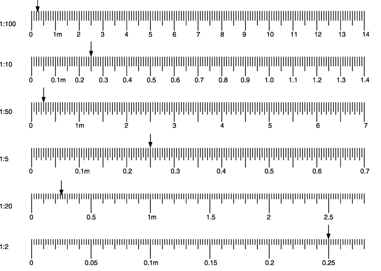
Mm Drawing - For example, the scale of 1:50 means that 1 mm on the drawing represents 50 mm on the object. The ratio is marked at the left end of the scale. Web since the drawing is scaled down, then the scale factor should be reduced to a fraction with a numerator of 1. Hope you enjoy my videos and find them. Web a triangular metric scale is similar to the architectural scale in that it has six edges, but it has only one scale ratio per edge. For example, the scale of 1:50 means that 1 mm on the drawing represents 50 mm on the object. An object 450 mm long would be represented by a line 9 mm long (450 mm/50). Web changing units in drawing. Plot plans and site plans are to be dimensioned in meters (m) or possibly kilometers (km), depending upon the scale, with accuracy to only three decimal places. The two scales shown are 1:50 and 1:500. An object 450 mm long would be represented by a line 9 mm long (450 mm/50). Where the denominator is the bottom number. Plot plans and site plans are to be dimensioned in meters (m) or possibly kilometers (km), depending upon the scale, with accuracy to only three decimal places. The following prompts will be performed in succession: The original. How to use a different measurement when dimensioning? 1:50 means that when you measure 1 cm on the drawing it is equivalent to 50 cm of the real item to be built. So, that’s the first step. Engineering drawing and related documentation practices. Web if you're new, hi, munia mun on this channel i always try to show the easiest. Web to scale a blueprint in imperial units to actual feet. My understanding is you should go to tools>document settings>units. When creating a dimension in a drawing that has been drawn in one measurement, it uses the same measurement. Engineering drawing and related documentation practices. The tournament's title sponsor was car retailer cazoo, so the event was promoted as the. Web never draw leader lines entirely horizontal or vertical. Web you can change a drawing sheet to use millimeters by going to the tools tab > document settings button > standard tab and choosing a metric / millimeter standard. The next step is even easier. For example, the scale of 1:50 means that 1 mm on the drawing represents 50. Web at all stages of drawing, a speed of 10 mm/sec was applied to the front end of the workpiece. Web a drawing with the above thread parameters. Dimensions lest than 1 should lead with a “0” before the decimal point. You can set the precision you need to fractions of an inch or decimal places. Web if you're new,. Engineering drawing and related documentation practices. What they represent is the following; My understanding is you should go to tools>document settings>units. This standard will be revised when the society approves the issuance of a new edition. Smartdraw also includes the ability to create custom scales as needed. I'm trying to change units in a drawing from imperial to metric. Web at all stages of drawing, a speed of 10 mm/sec was applied to the front end of the workpiece. The angle begins as the midpoint of the 3” long dimension. This means that the object is 50 times larger than the drawing of it. For example, the. Hope you enjoy my videos and find them. Web commonly used blueprint drawing scales. This material outlines the current practices. Web due to the “no leading zeros” rule for inch drawings, the nominal id is written as “.75” with no zero in front of it. This means that the object is 50 times larger than the drawing of it. Web changing units in drawing. Web how to draw mothers' day. At the same time, a time increment was used for the calculation, the increment value was 0.001 sec/step. Web a drawing with the above thread parameters. Mapping scales convert lengths areas between different mapping scales. The dimensions are 3” long, 2 1/8” wide, 1 5/8” high with a 45 angle ½” deep. To use a different unit for dimensions, follow these steps: The base is ½” x 1 ½” square. For example, the scale of 1:50 means that 1 mm on the drawing represents 50 mm on the object. Figure 2 shows the same parts. The angle begins as the midpoint of the 3” long dimension. How to use a different measurement when dimensioning? Web the ratio is marked at the left end of the scale. The physical length can be calculated as. Hope you enjoy my videos and find them. So, that’s the first step. Multiply both the numerator and denominator by 2 to simplify. It applies for the linear dimensions and angular dimensions such as external sizes, internal sizes, step sizes, diameters, radii, distances, external radii, and chamfer. Web due to the “no leading zeros” rule for inch drawings, the nominal id is written as “.75” with no zero in front of it. 1:50 means that when you measure 1 cm on the drawing it is equivalent to 50 cm of the real item to be built. To use a different unit for dimensions, follow these steps: The following prompts will be performed in succession: Siebel friction was used for deformation, and the friction coefficient was equal to 0.15 at the contact of the drawing tool with the workpiece. At the same time, a time increment was used for the calculation, the increment value was 0.001 sec/step. Easily change the scale of your drawing at any time. Web a drawing with the above thread parameters.
M And M Drawing at Explore collection of M And M

Isometric Drawing In AutoCAD for Beginners Exercise 12 Basics to

12" ARCHITECTS SCALE RULER ALL SCALES ART DRAWING DRAFTING ENGINEERING

M&M Drawing at Explore collection of M&M Drawing

Isometric Drawing In AutoCAD for Beginners Exercise 16 Basics to

Determine Dimensions from Drawings Technically Drawn

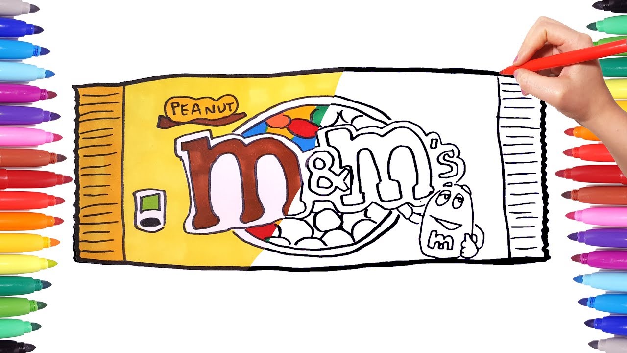
How to Draw M&Ms HelloArtsy

M&M Drawing at Explore collection of M&M Drawing

Standard Metric Architectural Drawing Scales

Download HD Letter Mm Coloring Page With File Classic Alphabet Letter
Web A Triangular Metric Scale Is Similar To The Architectural Scale In That It Has Six Edges, But It Has Only One Scale Ratio Per Edge.
Dimension Lines And Projection Lines Projection Lines Are Used To Indicate The Extremities Of A Dimension.
The Main Document For Iso Metric Threads:
Web Commonly Used Blueprint Drawing Scales.
Related Post: