Orthographic Drawing Symbol
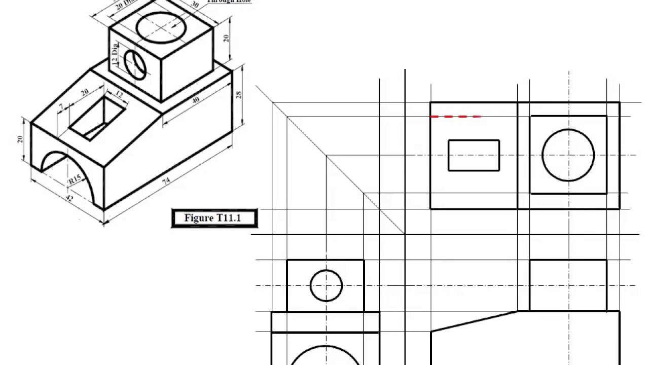
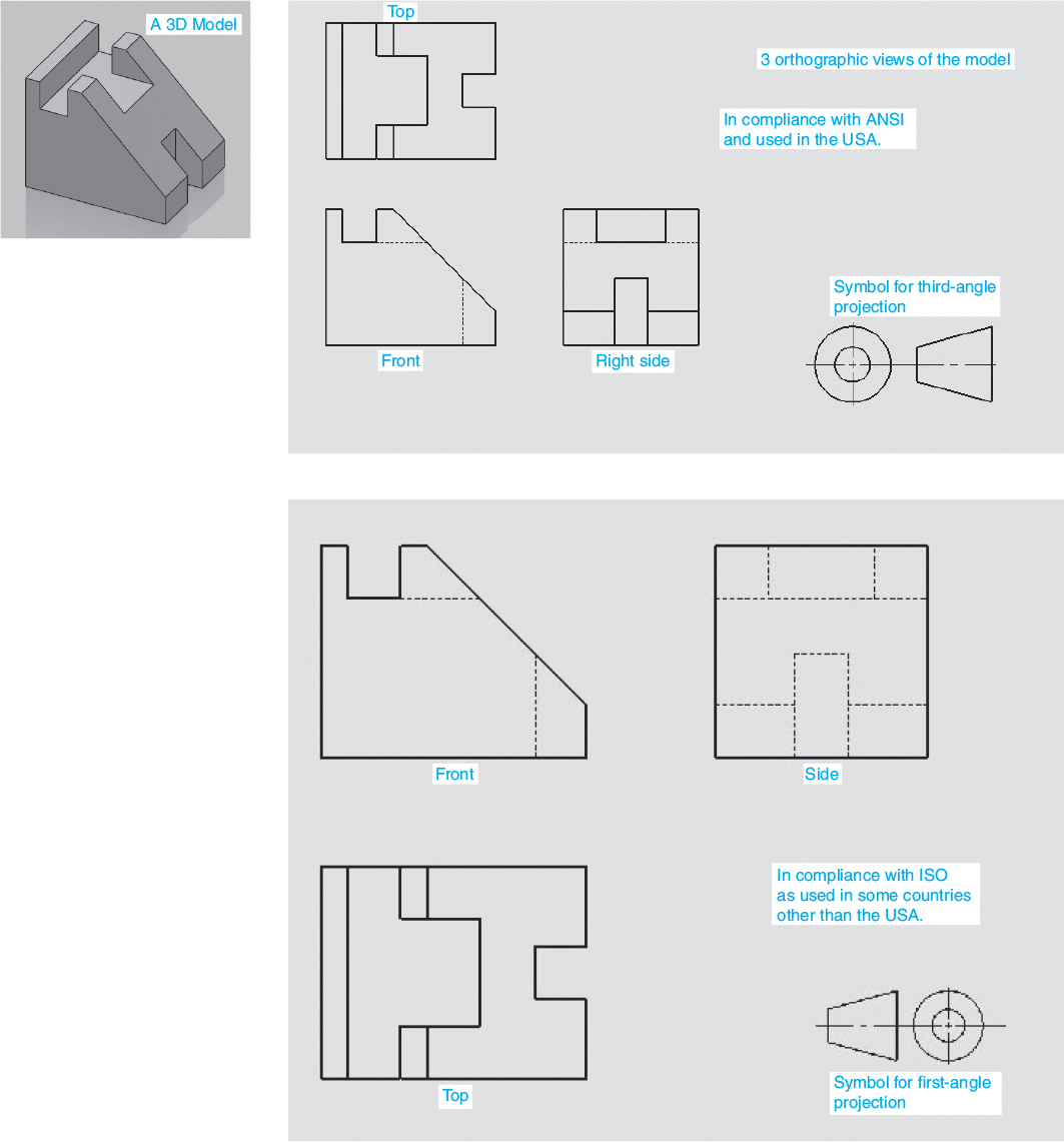
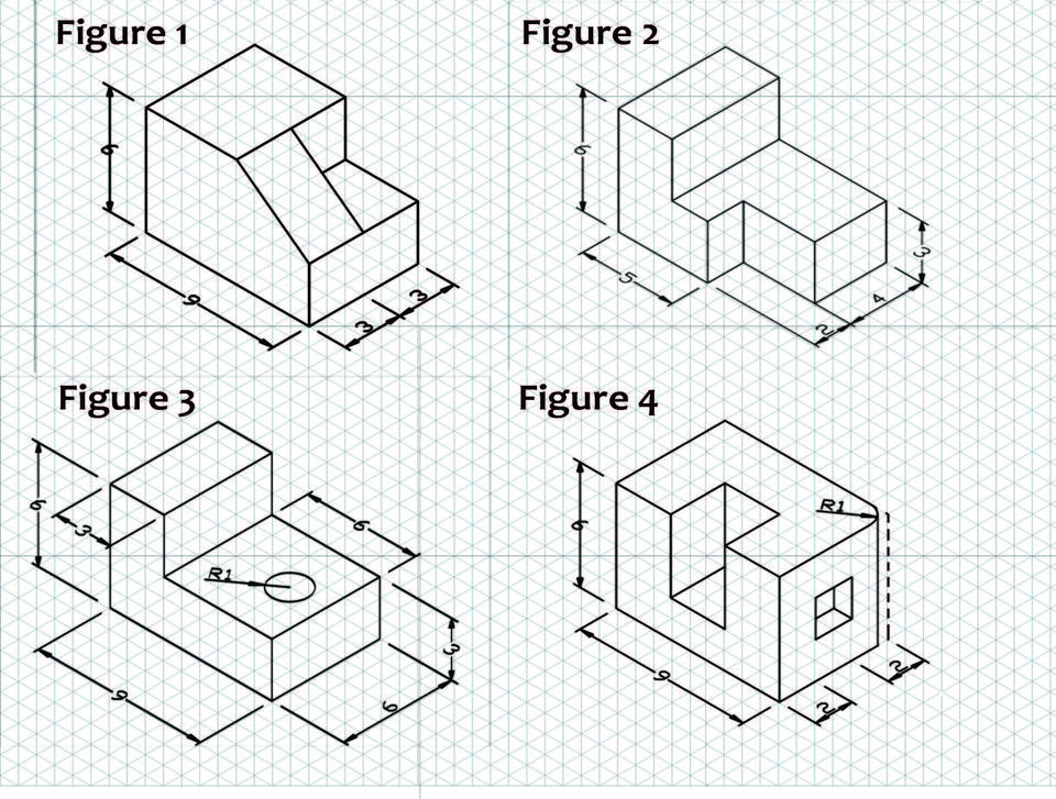
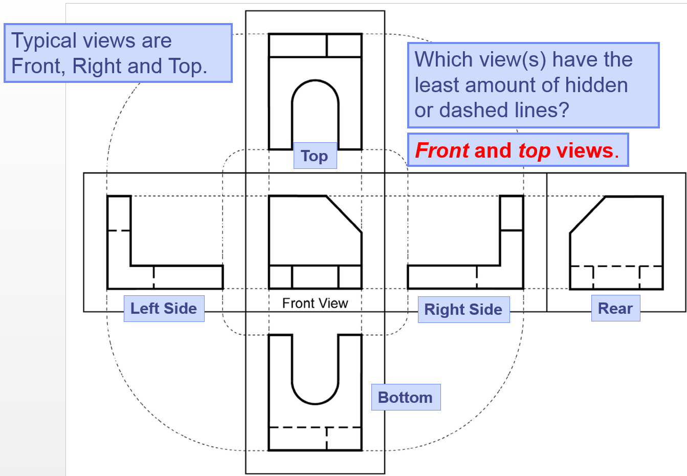
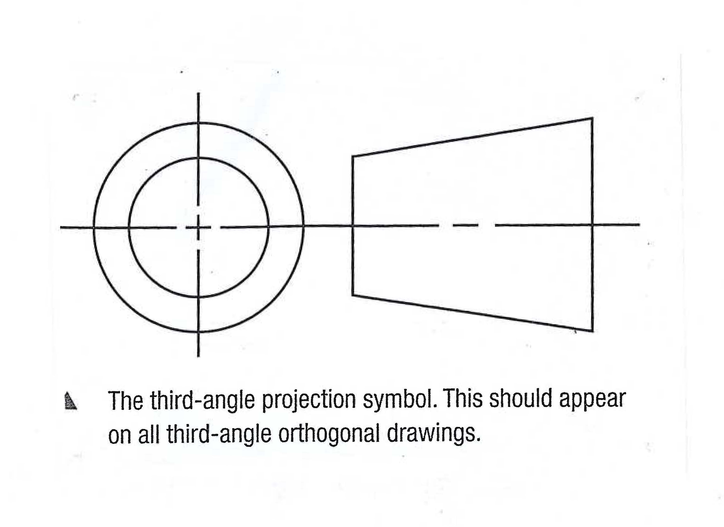
Orthographic Drawing Symbol - Web for engineering applications, the orthographic projection is the tool of choice in most cases. Web however, a 3d object represented in a 2d plane is called an orthographic projection. Do not dimension the drawing. Sectional cross hatching symbols for a number of common materials are shown below. 4/5 (17 reviews) Each symbol represents the views of a cone from that angle view. Orthographic projection of the stepped block with the surfaces numbered for reference. Web an orthographic drawing is only complete when dimensions, scale and orthographic symbols are added (shown below). In this video we take a quick look at how to use the symbols you need to use. Add the third angle orthographic drawing symbol. Another example of first angle orthographic projection is shown below. Make a the lowest point of the drawing. Do not dimension the drawing. An engineering drawing is a type of technical drawing that is used to convey information about an object. This is is done making multiple two. The orthographic projection is a way of drawing an object as seen from three different directions. Web an orthographic drawing, also known as an orthographic projection, is a drawing in which a three dimensional object is represented in two dimensions. Mathematically, an orthographic projection is created by defining a flat projection plane, and then projecting the features of the 3d. In this video we take a quick look at how to use the symbols you need to use. Web orthographic projection 8: All 3 views are shown in the final orthogonal. You can use an orthographic drawing to better see objects in 3d, or to plan a complex object or environment! Web an orthographic drawing, also known as an orthographic. Web normally when drawing in first or third angle projection a symbol is drawn which clearly shows which angle of projection has been used. Web an orthographic drawing is only complete when dimensions, scale and orthographic symbols are added (shown below). Geometrical figures are in two dimensions, hence they may be drawn to their actual sizes and shapes on a. Web what is an orthographic drawing? Web first and third angle projections use these symbols on a diagram to indicate which projection they are: The 6 principal views are created by looking at the object (straight on) in the directions indicated. This is is done making multiple two. Web orthographic projection is a formal drawing language. Web orthographic projection is a form of parallel projection in which the top, front, and side of an object are projected onto perpendicular planes. Apply different line weights to construction lines and bold lines. Both third and first angle symbols show the circular top view of a cone and the right view of the cone. Orthographic projections have a set. Label neatly in block letters. Orthographic projection of the stepped block with the surfaces numbered for reference. All 3 views are shown in the final orthogonal. The 6 principal views are created by looking at the object (straight on) in the directions indicated. Task 5.6 convert the orthographic drawing shown below into an isometric drawings. Usually, a number of drawings are necessary to completely specify even a simple component. Web orthographic projection is a formal drawing language. Whatever your drawing projection you will use common drawing symbols and notations. The difference in symbols is where the right view of the cone is located. 113k views 8 years ago. Web this symbol indicates the projection method used in the drawing. Geometrical figures are in two dimensions, hence they may be drawn to their actual sizes and shapes on a sheet of paper as it is also in two dimensions. Add the scale you have used. Add the third angle orthographic drawing symbol. The orthographic projection is a way of. Web normally when drawing in first or third angle projection a symbol is drawn underneath which clearly shows which angle of projection has been used. Web orthographic projection is a formal drawing language. Usually, a number of drawings are necessary to completely specify even a simple component. Add the third angle orthographic drawing symbol. Web draw the third angle symbol. An engineering drawing is a type of technical drawing that is used to convey information about an object. The difference in symbols is where the right view of the cone is located. Web an orthographic drawing, also known as an orthographic projection, is a drawing in which a three dimensional object is represented in two dimensions. A common use is to specify the geometry necessary for the construction of a component and is called a detail drawing. Task 5.6 convert the orthographic drawing shown below into an isometric drawings. Do not dimension the drawing. Mathematically, an orthographic projection is created by defining a flat projection plane, and then projecting the features of the 3d object onto the plane along lines (or projectors) which are perpendicular to the. This site provides a wealth of technology information sheets for pupils and teachers. Web normally when drawing in first or third angle projection a symbol is drawn underneath which clearly shows which angle of projection has been used. In this video we take a quick look at how to use the symbols you need to use. Web what is an orthographic drawing? Solution for task 5.6 convert the orthographic drawing shown below into an isometric drawings. Web first and third angle projections use these symbols on a diagram to indicate which projection they are: Web the first angle symbol is shown at the top left of figure 2. Usually, a number of drawings are necessary to completely specify even a simple component. Sectional cross hatching symbols for a number of common materials are shown below.
Symbols For 1st And 3rd Angle Projection Design Talk

drafting standards third angle projection and first angle projection
What Is Orthographic Drawing Sketch Coloring Page

symbol for orthographic drawing Orthographic Projection, Orthographic

First vs Third Angle Orthographic Views GD&T Basics

Open pdf and read instructions and draw a orthographic drawing on blank
Third Angle Orthogonal Drawing Symbol pichead
Three View Orthographic Drawing at GetDrawings Free download
Drafting Teacher blog Orthographic Projection
O1 Technical drawing in context BELLARINE SECONDARY COLLEGE
They Build Shapes Using Cube Blocks And Then Draw Orthographic And Isometric Views Of Those Shapes—Which Are The Side Views, Such As Top, Front,.
Before Studying This Lesson I Need To Make Sure That I Know How To:
All 3 Views Are Shown In The Final Orthogonal.
Orthographic Projections Have A Set Of Standard Lines To Show Different Aspects Of The.
Related Post: