Pitot Flow Chart
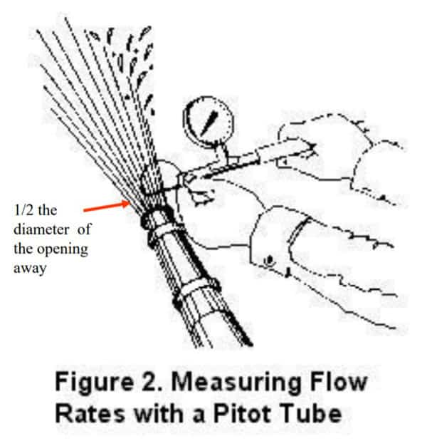
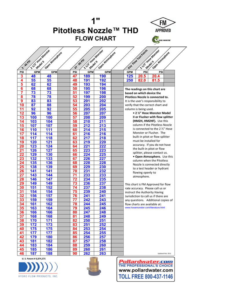
Pitot Flow Chart - Vt = √ 2 ρa(pt − pa) = √2q ρa. For use with allenco pitot tube or similar pitot tube. Click here to print out this flow chart. = flow coefficient (see “how to order”) In this demonstration, stagnation pressure is measured with a manometer. In this post, we will take a closer look at the pitot tube flow meter. Web the adjacent chart does this graphically for all subsonic airspeeds. Web flow test chart calculator smooth radius sharp square raised pressure f l o w i n g p m b y p i p e s i z e chart values have been rounded to the nearest 5 gpm. Fm approved flowbustertm flow chart. Due to low dynamic pressure (head) the readings will be inaccurate. Insufficient pressure drop on residual hydrant. If the coefficient of your hydrant outlet is 0.9, multiplying 2,526 x 0.9 finds the actual rate of flow: Web in other words, if your pitot pressure is 28 psi and your orifice size is 4, your theoretical discharge according to the table is 2,526 gpm. H2o) = k2 x d1 4 x x. • 2 ½” use this column if the hose monster is used without a nozzle insert. But let’s start from the beginning. = flow coefficient (see “how to order”) 29.71d2√np , d = bore diameter, np = nozzle pressure measured with pitot gauge (psi). Web pitot gauges make it simple to quickly measure the pressure of flowing water from fire. Table 4.10.1(a) two hydrant flow test with a calibrated flow device. Web to calculate the actual flow for each hydrant butt, first convert the velocity pressure reading(s) on the pitot gauge to gallons per minute byusing the pitot gauge conversion chart (far. 4.3 subsonic relations between compressible and incompressible dynamic pressure. For constant density (incompressible) flow bernoulli’s equation reduces to.. Essential for fire pump testing. Tip diameter pitot pressure psi 3/4” 40 106. H2o) = k2 x d4 x 32.14. For a given pitot pressure in psi, this flow chart will determine your flow in gpm for the specific nozzle diameter used. We will discuss the different pitot tube types and look for the underlying principles that ensure that the. Fm approved flowbustertm flow chart. What is a pitot tube? In this demonstration, stagnation pressure is measured with a manometer. Elevation differential between test and. Table 4.10.1(a) two hydrant flow test with a calibrated flow device. Steam or any gas (steam requires min p of 10 h2o): Caution—be sure to read instructions manual before using. 29.71d2√np , d = bore diameter, np = nozzle pressure measured with pitot gauge (psi). Insufficient pressure drop on residual hydrant. For constant density (incompressible) flow bernoulli’s equation reduces to. Web flow chart the readings on this chart are based on pitot diameter orifice. Essential for fire pump testing. Click here to print out this flow chart. Ve = vc + δvc. 4.3 subsonic relations between compressible and incompressible dynamic pressure. 4.3 subsonic relations between compressible and incompressible dynamic pressure. Caution—be sure to read instructions manual before using. Actual results may vary as inaccuracies can occur due to variations in the blade postion in the stream. Web allenco flow testing pitot kit with case, gauge, charts. If the coefficient of your hydrant outlet is 0.9, multiplying 2,526 x 0.9 finds the. H2o) = k2 x d1 4 x x 128,900. Insufficient pressure drop on residual hydrant. Web allenco flow testing pitot kit with case, gauge, charts. Tip diameter pitot pressure psi 3/4” 40 106. Please contact us if you need values for pressures other than those shown. Essential for fire pump testing. Web to calculate the actual flow for each hydrant butt, first convert the velocity pressure reading(s) on the pitot gauge to gallons per minute byusing the pitot gauge conversion chart (far. Table 4.10.1(a) two hydrant flow test with a calibrated flow device. In this demonstration, stagnation pressure is measured with a manometer. Steam or any. Where incompressible dynamic pressure q is defined as pt − pa. Web to calculate the actual flow for each hydrant butt, first convert the velocity pressure reading(s) on the pitot gauge to gallons per minute byusing the pitot gauge conversion chart (far. Web flow chart the readings on this chart are based on pitot diameter orifice. In this post, we will take a closer look at the pitot tube flow meter. Actual results may vary as inaccuracies can occur due to variations in the blade postion in the stream. For testing fire pumps, nozzles and more. For constant density (incompressible) flow bernoulli’s equation reduces to. Web the sauermann pitot tubes, connected to a differential column of liquid manometer, with needle or electronic, enable to measure the dynamic pression of a fluid in movement in a pipe and determine its speed in m/s and its flow in m 3 /h. The static and the total impact pressure. Elevation differential between test and. = differential pressure (in in h2o) = flowrate. Tip diameter pitot pressure psi 3/4” 40 106. Web allenco flow testing pitot kit with case, gauge, charts. In this demonstration, stagnation pressure is measured with a manometer. But let’s start from the beginning. The accuracy of these flows are based upon theoretical discharge calculations.Pitot Pressure Flow Chart Pressure Nature
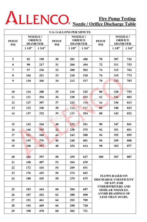
> Literature & Guides > Download Fire Pump Pitot Tube

Pitot Chart
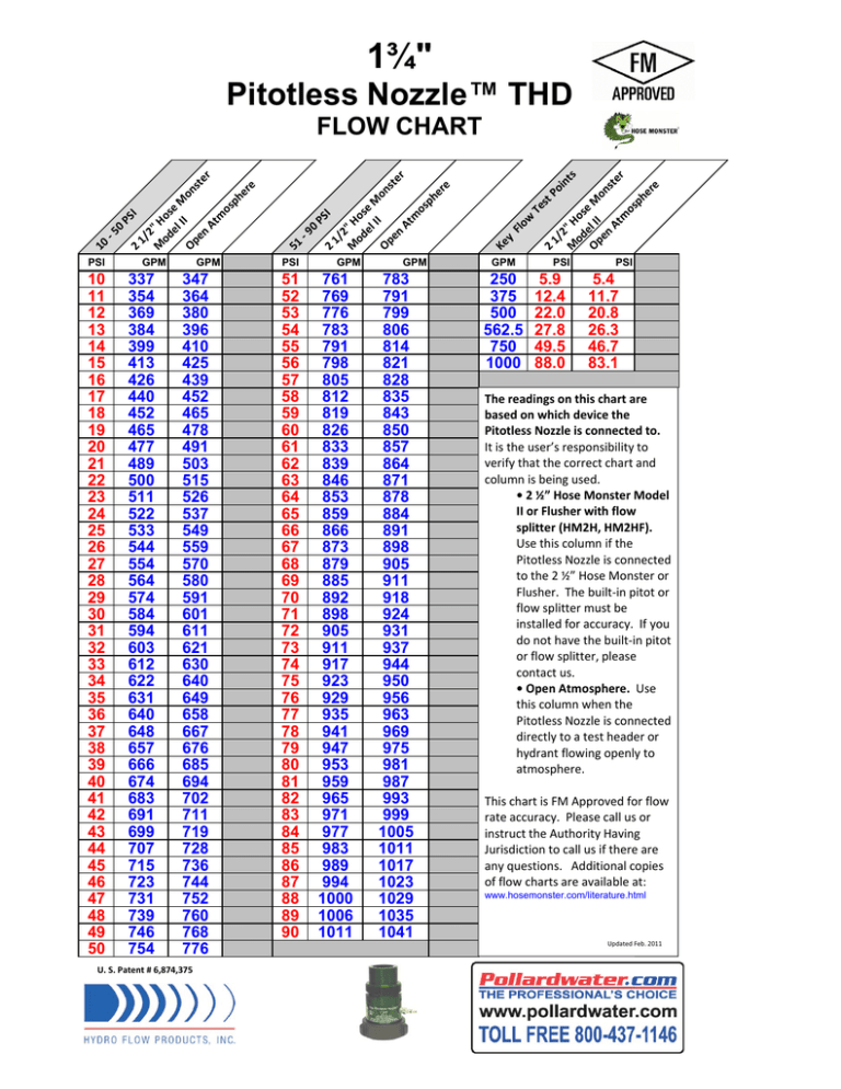
Pitot Gauge Flow Chart
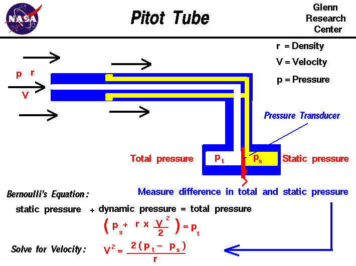
Pitot Tube Flow Chart
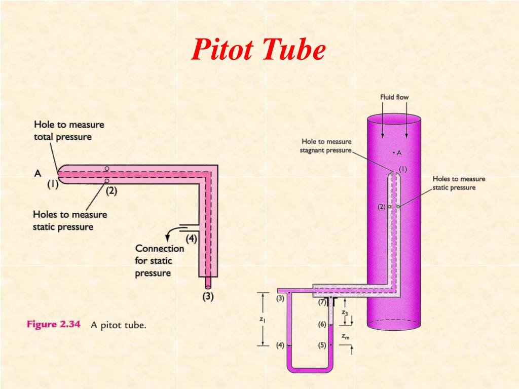
Pitot Tube Flow Chart
Pitot Psi Flow Chart
The PitotStatic System. by Ted Staggs April 5, 2020 by Ted How To
Pitot Chart

Pollardwater Pitot Flow Chart Best Picture Of Chart
Q2(Scfm) X Ssx (T + 460) P(In.h2O)= K2X D41X P X 16,590.
The Static Pressure Is The Operating Pressure In The Pipe, Duct, Or The Environment, Upstream To The Pitot Tube.
Click Here To Print Out This Flow Chart.
Web Pitot Tubes Were Invented By Henri Pitot In 1732 To Measure The Flowing Velocity Of Fluids.
Related Post:
