Thermistor Resistance Vs Temperature Chart
Thermistor Resistance Vs Temperature Chart - Web calculate the resistance in ohms of resistors connected in series by entering the value of each. Resistance chart thermistor @ 25°c ohms °f °c resistance 10k open infinite 32 0 32,630 41 5 25,380 50 10 19,890 59 15 15,710 68 20 12,490 77 25 10,000 86 30 8,057 95 35 6,531 104 40 5,326 113 45 4,368 122 50 3,601 131 55 2,985 140 60 2,487 149 65 2,082 158 70 1,751 176 80 1,255 194 90 917 212 100 680 short. Data in white refers to thermistors with ±0.2°c interchangeability. Web temperature / resistance chart 10,000 ω @ 77 °f temp °f ohms temp °f ohms temp °f ohms temp °f ohms 0 85,378 33 31,738 66 13,138 99 5,961 1 82,710 34 30,855 67 12,811 100 5,827 2 80,135 35 30,000 68 12,493 101 5,697 3 77,649 36 29,171 69 12,184 102 5,570 4 75,249 37 28,376 70 11,883 103 5,446 5 72,931 38 27,589 71 11,591 104. The heat dissipation constant is an expression in milliwatts of the power required to raise the temperature of a thermistor 1°c above the ambient. Of teflon encased thermistors add 100 to part no. The precon sensor has a dissipation constant in still air at 25°c of 2.7 mw/°c. Sensor tolerance is ±0.2°c in the range 0 to 70°c. Only thermistors with ±0.2°c interchangeability are available encased in teflon as standard parts. The top table can be helpful for curve fitting. This makes them ideal for accurate temperature measurement and control. Of teflon encased thermistors add 100 to part no. Temperature/resistance figures are the same for both types. Web thermistor resistance vs temperature chart. Web 10,000 ω type 3, ntc thermistor, greystone sensor codes 07 & 40 note: They are used for resistance thermometers in temperature measurement and all sterling sensors assemblies are made using this type of thermistor. In the typical control range (0°c to 40°c), 10k thermistors offer good sensitivity Web the following is a table of the correlation between the temperature and the resistance for the thermistor used in many pasco products. Web temperature/resistance figures. The relatively large negative response of an ntc thermistor means that even small changes in temperature can cause significant changes in their electrical resistance. This makes them ideal for accurate temperature measurement and control. They are used for resistance thermometers in temperature measurement and all sterling sensors assemblies are made using this type of thermistor. Resistance chart thermistor @ 25°c. The heat dissipation constant is an expression in milliwatts of the power required to raise the temperature of a thermistor 1°c above the ambient. This makes them ideal for accurate temperature measurement and control. Data in white refers to thermistors with ±0.2°c interchangeability. Web calculate the resistance in ohms of resistors connected in series by entering the value of each.. Data in white refers to thermistors with ±0.2°c interchangeability. Temperature/resistance figures are the same for both types. ±0.15°c @ 0°c (±0.28°f @ 32°f). The relatively large negative response of an ntc thermistor means that even small changes in temperature can cause significant changes in their electrical resistance. Data in purple refer to thermistors with ±0.1°c interchangeability. The top table can be helpful for curve fitting. Printed in canada copyrigh eyst e syst inc. Higher temperature applications generally use the higher resistance thermistors (above 10,000 ω) to optimize the resistance change per degree at the required temperature. Web ntc temperature thermistors have a negative electrical resistance versus temperature (r/t) relationship. Web the resistance temperature curve defines the. Web vishay dale ntc thermistors, resistance/temperature conversion www.vishay.com for technical questions, contact: The precon sensor has a dissipation constant in still air at 25°c of 2.7 mw/°c. Resistance chart thermistor @ 25°c ohms °f °c resistance 10k open infinite 32 0 32,630 41 5 25,380 50 10 19,890 59 15 15,710 68 20 12,490 77 25 10,000 86 30 8,057. ±0.22°c @ 25°c (±0.4°f @ 77°f); The relatively large negative response of an ntc thermistor means that even small changes in temperature can cause significant changes in their electrical resistance. Temperature increases (hence the ‘negative coefficient’). Web the chart below can be used as a referencing tool to find the relationship between a range of temperatures and resistance for pt100. Web the resistance temperature curve defines the temperature versus resistance characteristics, some curves change faster (steep slope), while others change more slowly (weaker slope). Web the chart below can be used as a referencing tool to find the relationship between a range of temperatures and resistance for pt100 rtd sensors. Printed in canada copyrigh eyst e syst inc. Both tables. Sensor tolerance is ±0.2°c in the range 0 to 70°c. Web calculate the resistance in ohms of resistors connected in series by entering the value of each. This makes them ideal for accurate temperature measurement and control. Only thermistors with ±0.2°c interchangeability are available encased in teflon as standard parts. Web ntc temperature thermistors have a negative electrical resistance versus. Temperature increases (hence the ‘negative coefficient’). Web ntc temperature thermistors have a negative electrical resistance versus temperature (r/t) relationship. The precon sensor has a dissipation constant in still air at 25°c of 2.7 mw/°c. ±0.22°c @ 25°c (±0.4°f @ 77°f); Negative temperature coefficient (ntc) thermistors have a resistance which reduces as the temperature rises (fig 1.). Of teflon encased thermistors add 100 to part no. The heat dissipation constant is an expression in milliwatts of the power required to raise the temperature of a thermistor 1°c above the ambient. Web the chart below can be used as a referencing tool to find the relationship between a range of temperatures and resistance for pt100 rtd sensors. Temperature graph as can be seen be the graph, the resistance of the thermistor drops very quickly. Web the resistance of the thermistor will change according to temperature, and should track with the following table. Web values for convectronics’ standard rtd and thermistor elements. Web temperature/resistance figures are the same for both types. Temperatures in multiples of ten can be found down the left axis, whilst for more precise readings you must move along the horizontal axis between one and nine. ±0.15°c @ 0°c (±0.28°f @ 32°f). Web 10,000 ω type 3, ntc thermistor, greystone sensor codes 07 & 40 note: Sensor tolerance is ±0.2°c in the range 0 to 70°c.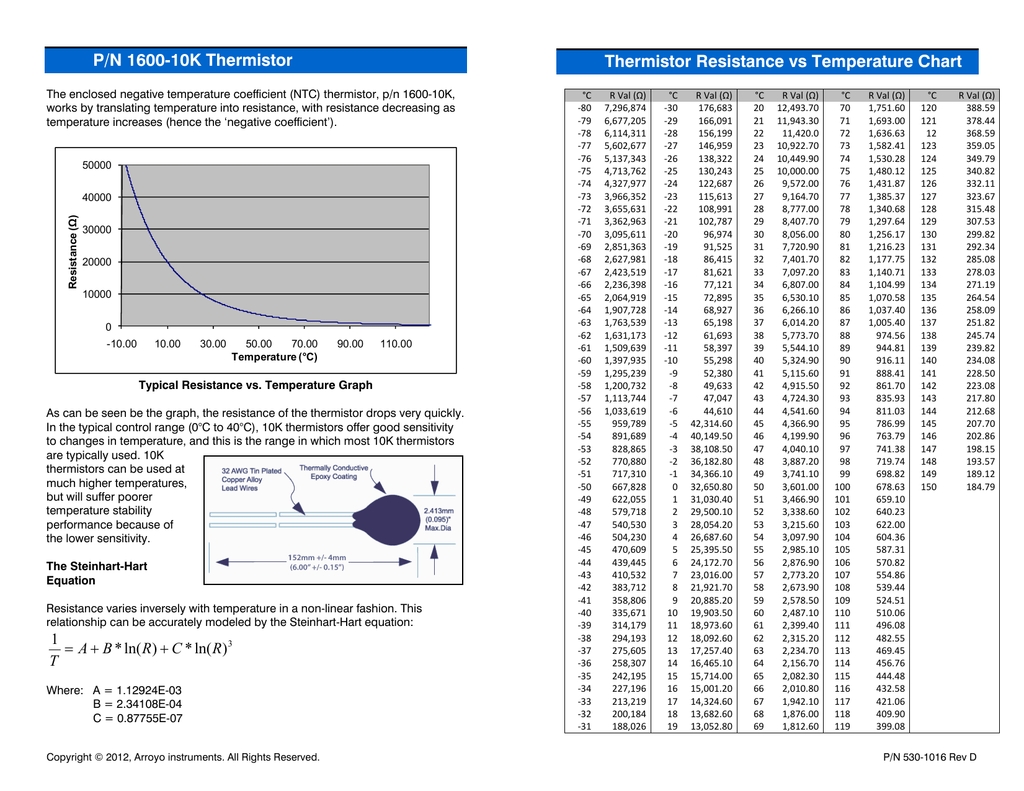
Thermistor Tables Resistance Vs Temperature

NTC Thermistor characteristic curveResistance ( R) vs. Temperature ( T
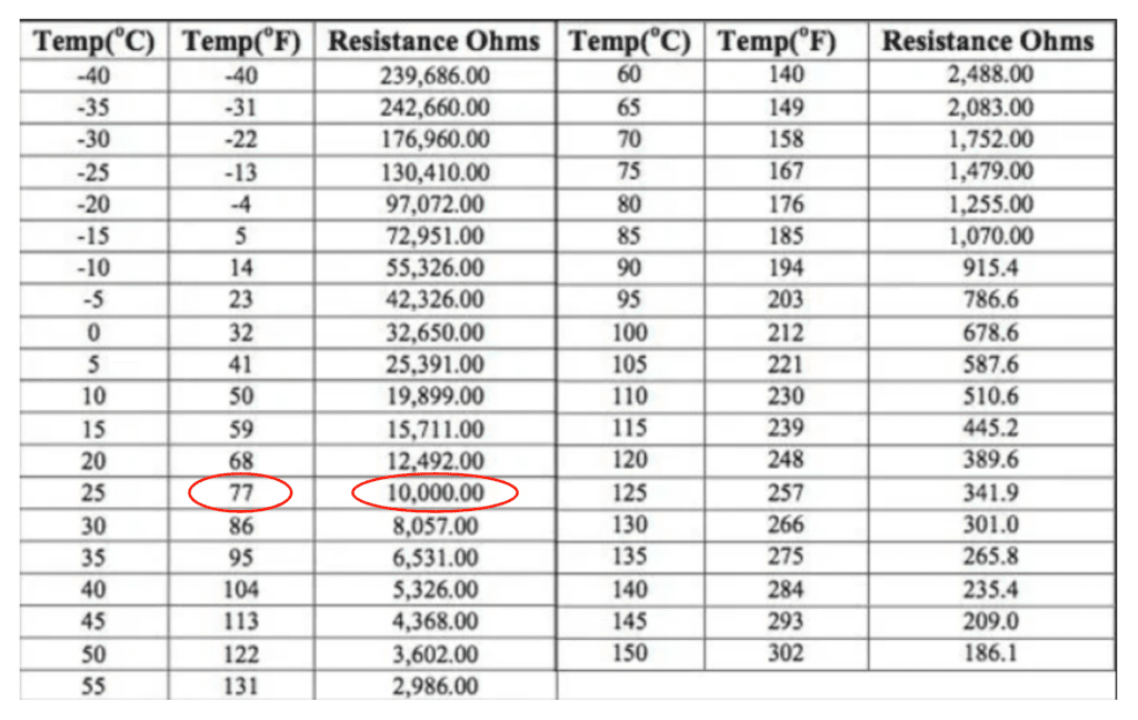
10k Thermistor Resistance Table Elcho Table
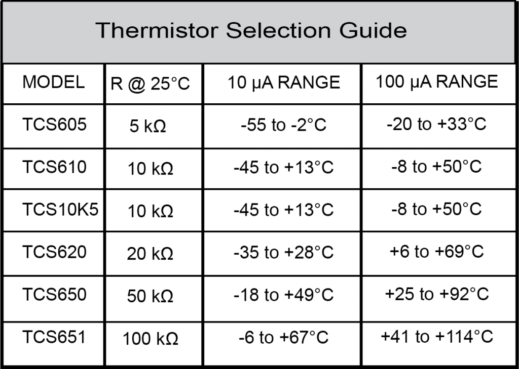
Thermistor Resistance How does it Calculate? Linquip

Arduino NTC Thermistor Tutorial How Thermistor Works and Interfacing

Thermistor Resistance Vs. Temperature
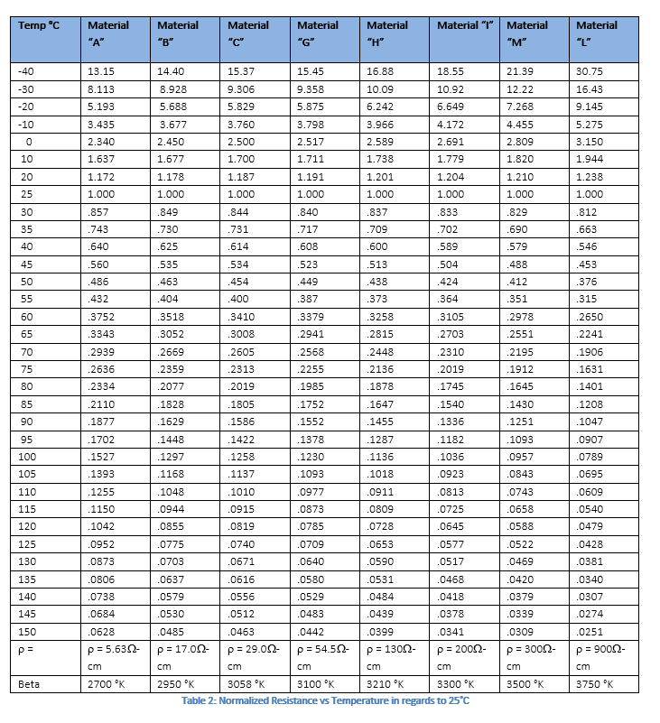
Enabling Higher Power Efficiency through Thermistorbased Temperature
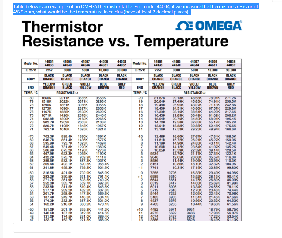
5k Ohm Thermistor Chart
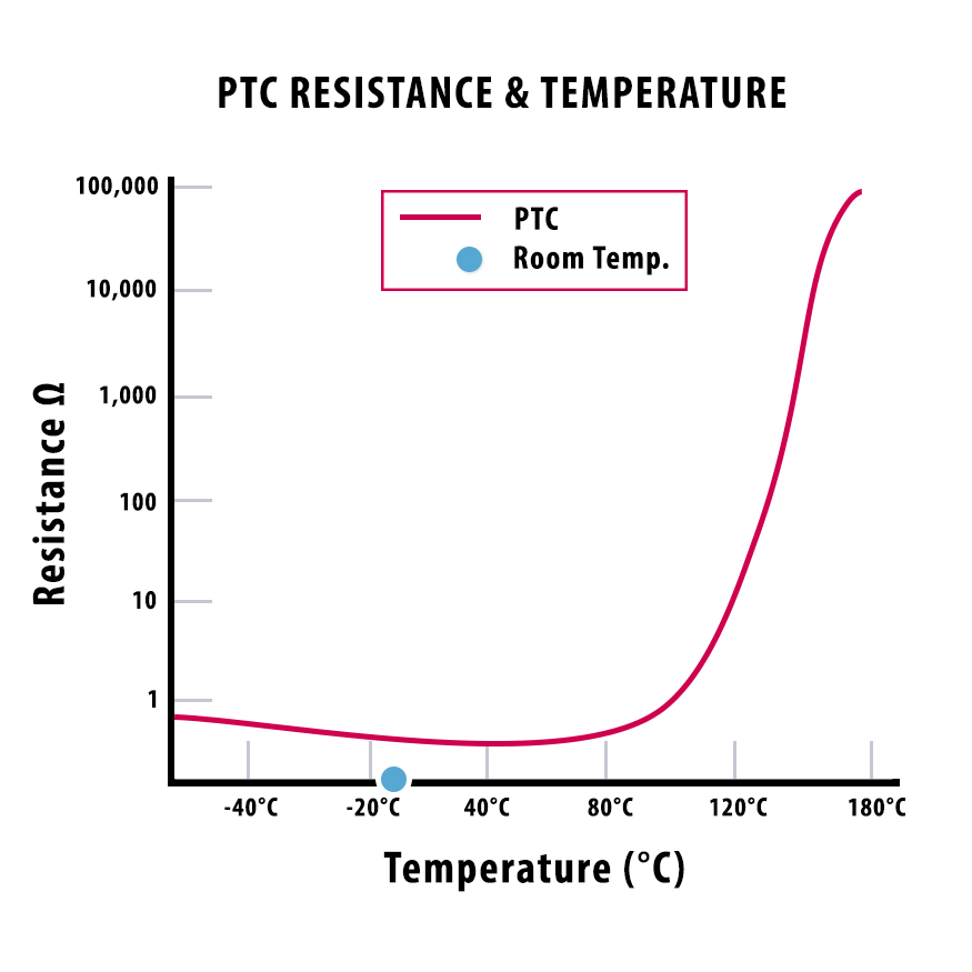
Everything you need to know about PTC thermistors

Resistance versus temperature response of a 1 k 25 C NTC thermistor
Web Calculate The Resistance In Ohms Of Resistors Connected In Series By Entering The Value Of Each.
The Top Table Can Be Helpful For Curve Fitting.
This Makes Them Ideal For Accurate Temperature Measurement And Control.
Temperature/Resistance Figures Are The Same For Both Types.
Related Post: