X Ray Kvp And Mas Chart
X Ray Kvp And Mas Chart - State all the important relationships in this chapter. If kvp is too high the image will be over exposed and too dark. Web make a technique chart. This chart is vital in the medical imaging field. The aim of this review was to develop a radiographic optimisation strategy to make use of digital radiography (dr) and needle phosphor computerised radiography (cr) detectors, in order to lower radiation dose and improve image quality for paediatrics. Matrix size, bit depth and file size The exposure must be linear: Matrix size, pixel size and image resolution; Web using the charts. Depending on the type of control panel, milliamperage and exposure time may be selected separately or combined as one factor, milliamperage/second (mas). This view demonstrates the distal femur and proximal tibia/fibula in their natural anatomical position allowing for assessment of suspected dislocations, fractures, localizing foreign bodies and osteoarthritis. Technical tips and supplemental views are provided to aid in obtaining optimal film quality using the most appropriate views. Based on the film, the parameters also provided good. Matrix size, pixel size and image. Web exposure chart small medium large small medium large. Web optimisation of the kvp, mas, and additional beam filtration combination for common paediatric projections, detector types, and pathology detectability requirements. Matrix size, bit depth and file size Define all the key terms in this chapter. Matrix size, pixel size and image resolution; To assist you in developing your own technique guide, factors in each highlighted mas and kvp cell may be changed and subsequent cells will adjust accordingly. You can use it to image animals in a veterinary setting and humans in a medical setting. Web the primary exposure technique factors the radiographer selects on the control panel are milliamperage (ma), time. To assist you in developing your own technique guide, factors in each highlighted mas and kvp cell may be changed and subsequent cells will adjust accordingly. This is based on the observation of the phantom structures that can be seen on the radiograph using these exposure parameters. If kvp is too high the image will be over exposed and too. Define all the key terms in this chapter. State all the important relationships in this chapter. State the purpose of automatic exposure control (aec) in radiography. Computer processing of the digital data; Differentiate among the types of radiation detectors used in aec systems. Matrix size, bit depth and file size State all the important relationships in this chapter. Based on the film, the parameters also provided good. Matrix size, pixel size and image resolution; So, what is a technique chart? Web the primary exposure technique factors the radiographer selects on the control panel are milliamperage (ma), time of exposure, and kilovoltage peak (kvp). This chapter is designed as a quick reference guide to radiographic positioning and technique. Matrix size, pixel size and image resolution; Web make a technique chart. Web exposure chart small medium large small medium large. Differentiate among the types of radiation detectors used in aec systems. Recognize how the detector size and configuration affect the response of the aec. Tube voltage, in turn, determines the quantity and. Web exposure chart small medium large small medium large. Only two papers assessed the efficacy of exposure adjustment systems. Describe how the photon energy, radiographic contrast and scale of contrast vary as the kvp is changed. State all the important relationships in this chapter. 200 ma will produce twice as much radiation as 100 ma. Technical tips and supplemental views are provided to aid in obtaining optimal film quality using the most appropriate views. The aim of this review. This chapter is designed as a quick reference guide to radiographic positioning and technique. Describe how the photon energy, radiographic contrast and scale of contrast vary as the kvp is changed. If kvp is too high the image will be over exposed and too dark. Technical tips and supplemental views are provided to aid in obtaining optimal film quality using. If you set 80 kvp, the average energy will be 80 kvp. So, what is a technique chart? The aim of this review was to develop a radiographic optimisation strategy to make use of digital radiography (dr) and needle phosphor computerised radiography (cr) detectors, in order to lower radiation dose and improve image quality for paediatrics. Web the primary exposure technique factors the radiographer selects on the control panel are milliamperage, time of exposure, and kilovoltage peak (kvp). If kvp is too high the image will be over exposed and too dark. Based on the film, the parameters also provided good. Web define kvp and explain its relationship to ir exposure, the four image properties and patient dose. Technical tips and supplemental views are provided to aid in obtaining optimal film quality using the most appropriate views. Define all the key terms in this chapter. Systems that employ computed radiography (cr) or digital radiography (dr) should have a technique chart that is specific to each cr or dr image receptors. Web exposure chart small medium large small medium large. State the purpose of automatic exposure control (aec) in radiography. Matrix size, bit depth and file size Web exposure factors (kvp, ma, exposure time or mas settings) grid (if applicable) type and placement of gonadal shielding used. Web using the charts. Recognize how the detector size and configuration affect the response of the aec.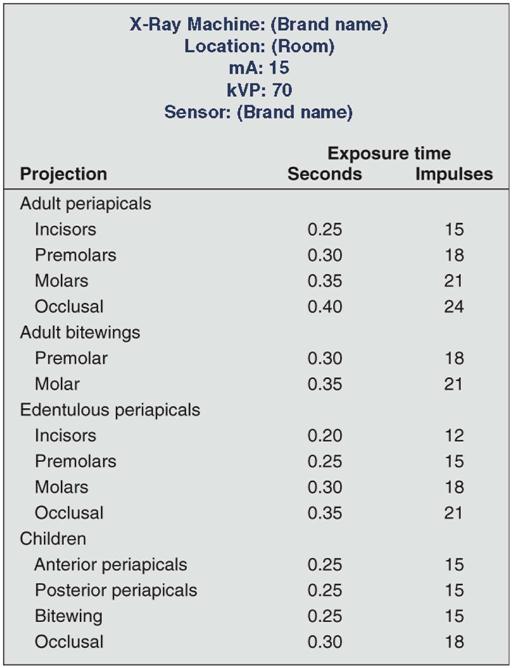
15. Quality Assurance and Infection Control Pocket Dentistry

Radiography Technique Exposure Factors KVP Energy of xrays
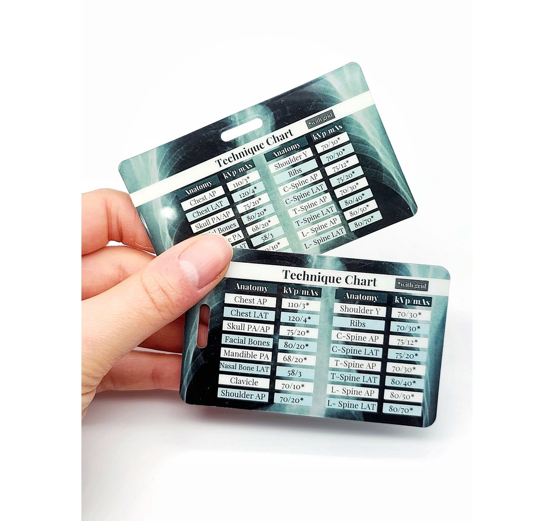
Buy Xray Technique Card Xray Mas and Kvp Chart Radiology Online in
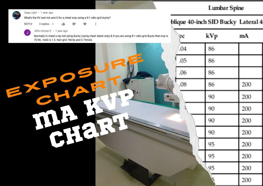
Relevance of Exposure Chart with HighFrequency XRay Machine
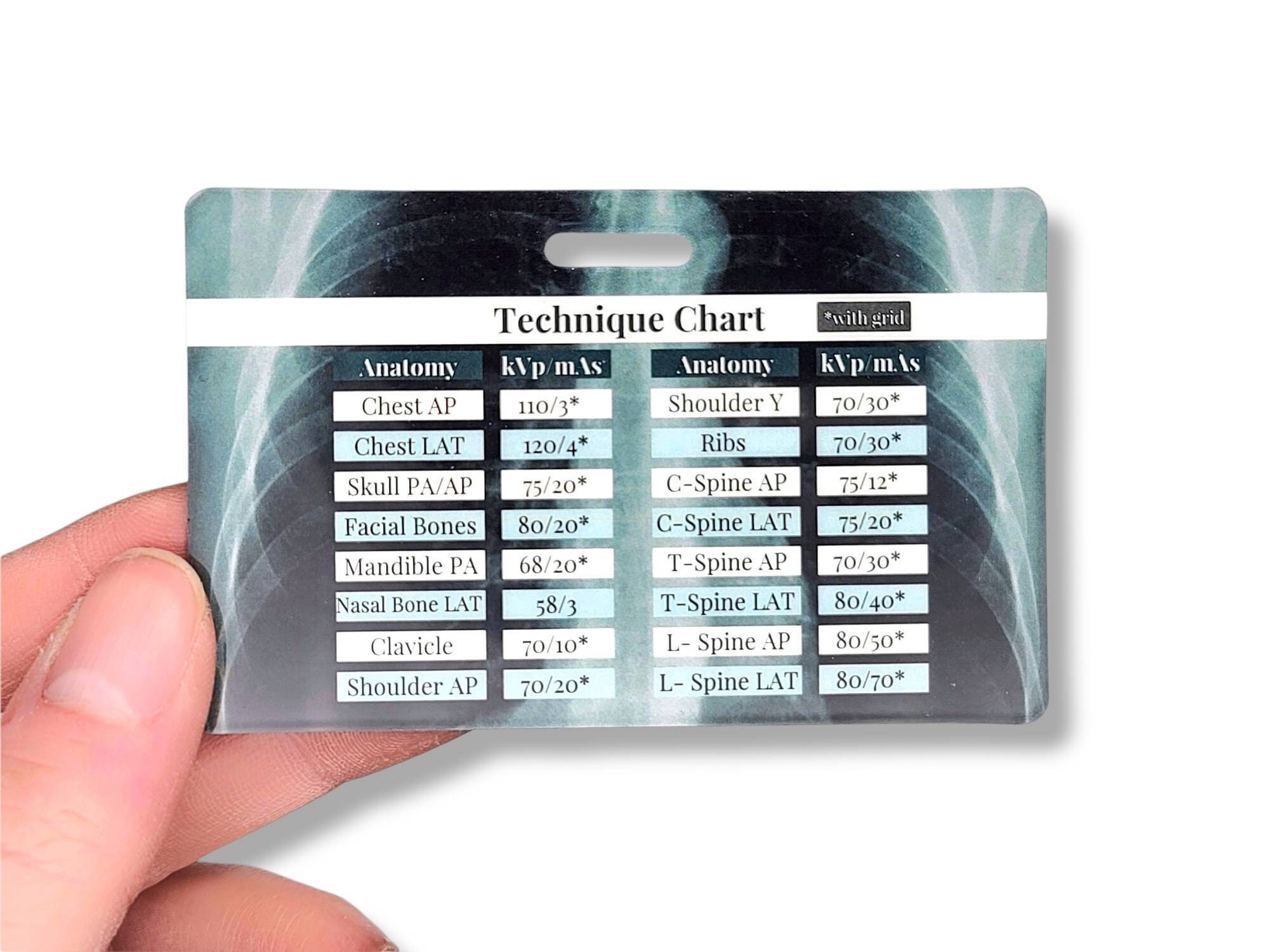
Human Kvp And Mas Technique Chart

kVp/MAS Ranges for Radiology
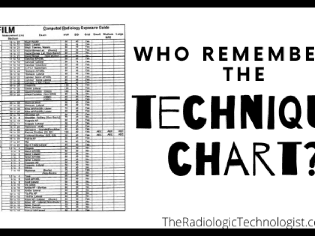
A Fixedkvp Technique Chart Uses Which of the Following WilliehasPugh

Xray Kvp And Mas Chart

Rad Tech CE, ASRT, ARRT® CE, Category A Credits Radiology Continuing

The measured Xray outputs at different currents (mAs) in different
This Is Based On The Observation Of The Phantom Structures That Can Be Seen On The Radiograph Using These Exposure Parameters.
This View Demonstrates The Distal Femur And Proximal Tibia/Fibula In Their Natural Anatomical Position Allowing For Assessment Of Suspected Dislocations, Fractures, Localizing Foreign Bodies And Osteoarthritis.
Depending On The Type Of Control Panel, Milliamperage And Exposure Time May Be Selected Separately Or Combined As One Factor, Milliamperage/Second (Mas).
You Can Use It To Image Animals In A Veterinary Setting And Humans In A Medical Setting.
Related Post: